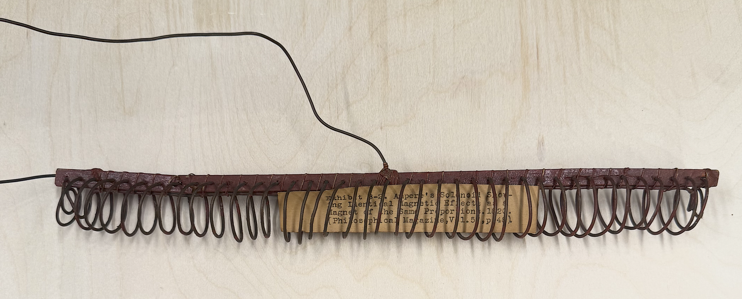
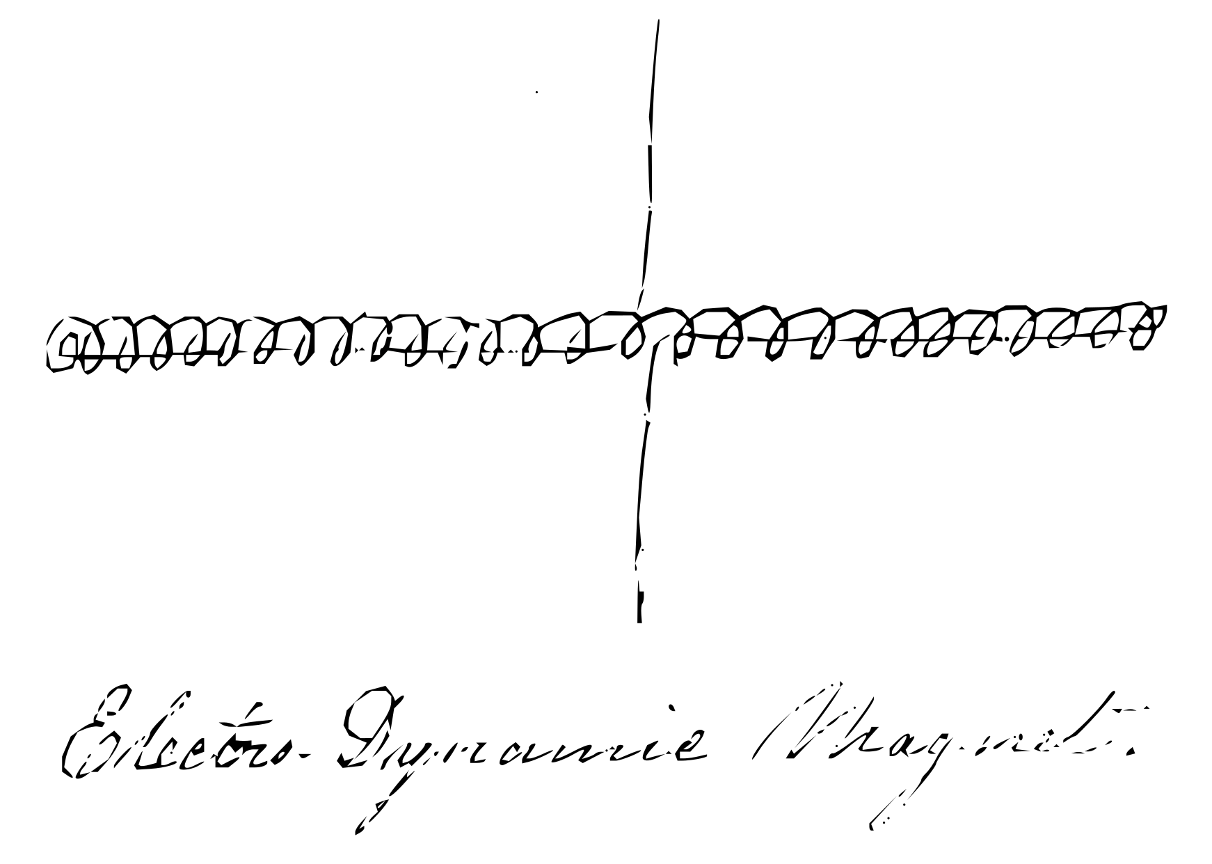
Henry Clay Cameron’s notes from Joseph Henry’s_59th_Lecture: Volume 15 (1820)
COMSOL Simulations // June-August 2026
Project 1: Permanent Bar Magnet and Electromagnet
This project aimed to model a 3-dimensional permanent bar magnet and an electromagnet in order to demonstrate the similarities between their magnetic field lines. Additionally, this serves as an introduction into working with the Magnetic Fields package. After assigning the proper physics, the field lines shown in both models were adjusted to better simulate the ideal diagrams in textbooks.
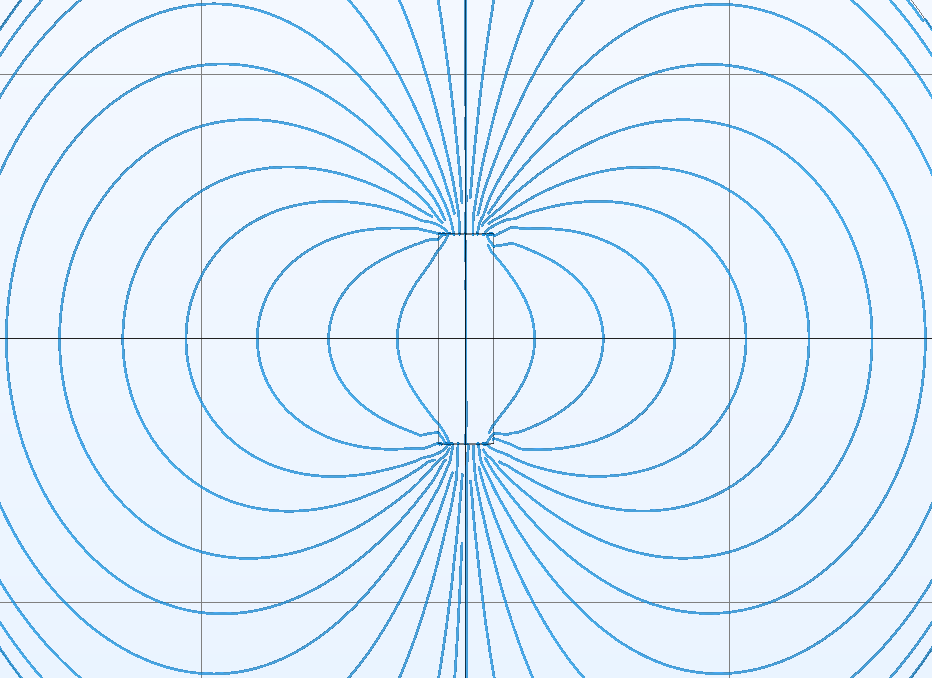
Bar Magnet Field Lines – June 29 2026 – COMSOL File Version 6.3
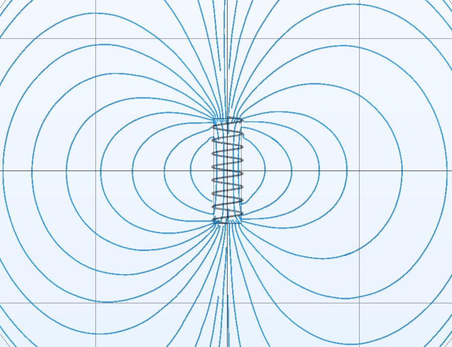
Electromagnet Field Lines – June 30 2026 – COMSOL File Version 6.3
Project 2: Horseshoe Electromagnet and an Iron Bar
This project aimed to model a 3-dimensional horseshoe electromagnet in order to simulate its magnetic field lines. An iron rod was added to the simulation to demonstrate the principle of magnetic permeability and model magnetic field and flux concentration. A force calculation was done on the iron bar to plot magnetic force vs displacement of bar towards the electromagnet. The motion of the iron bar was accomplished by performing a parametric sweep of a range of the bar’s possible distances from the electromagnet. After assigning the proper physics, the field lines shown were adjusted to better simulate the ideal diagrams in textbooks.
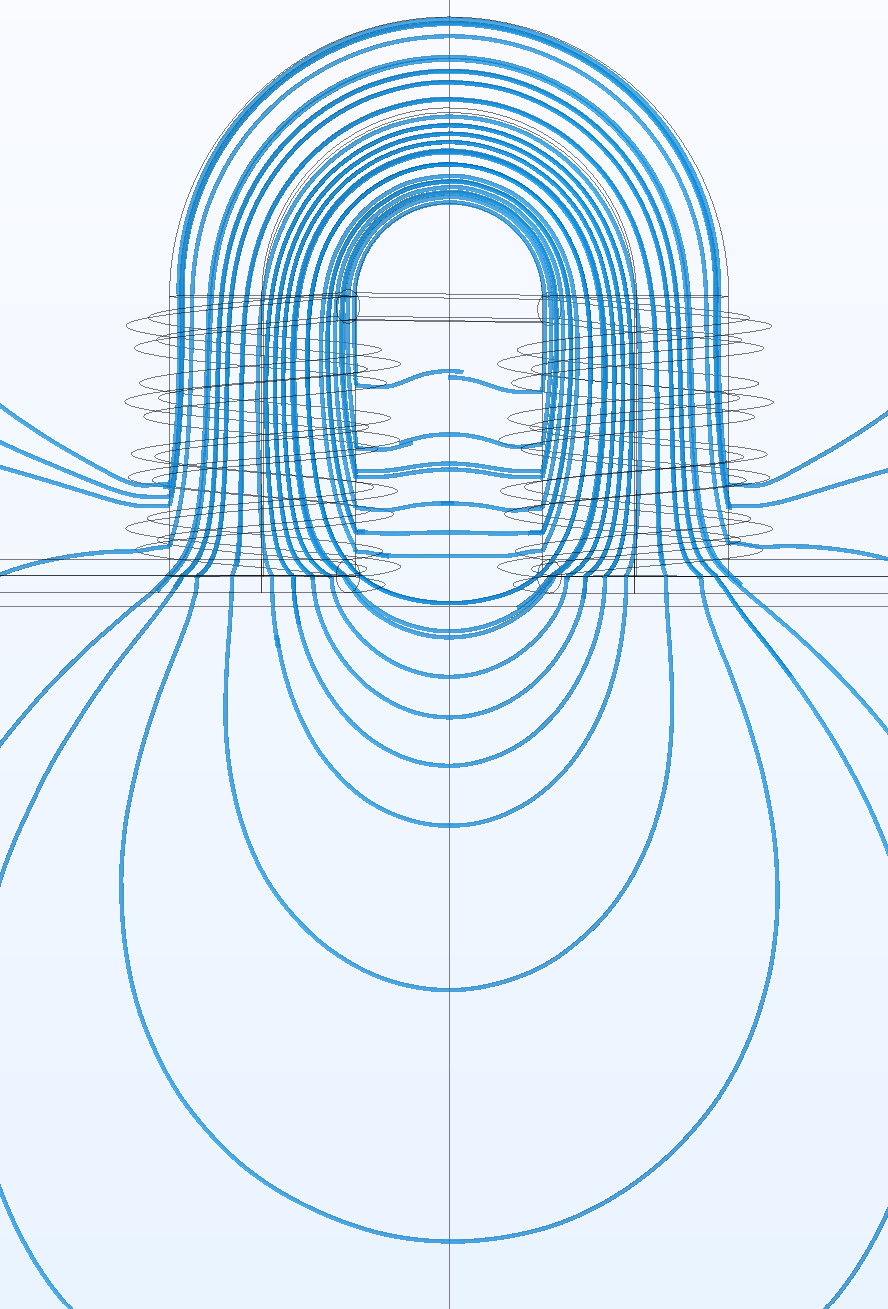
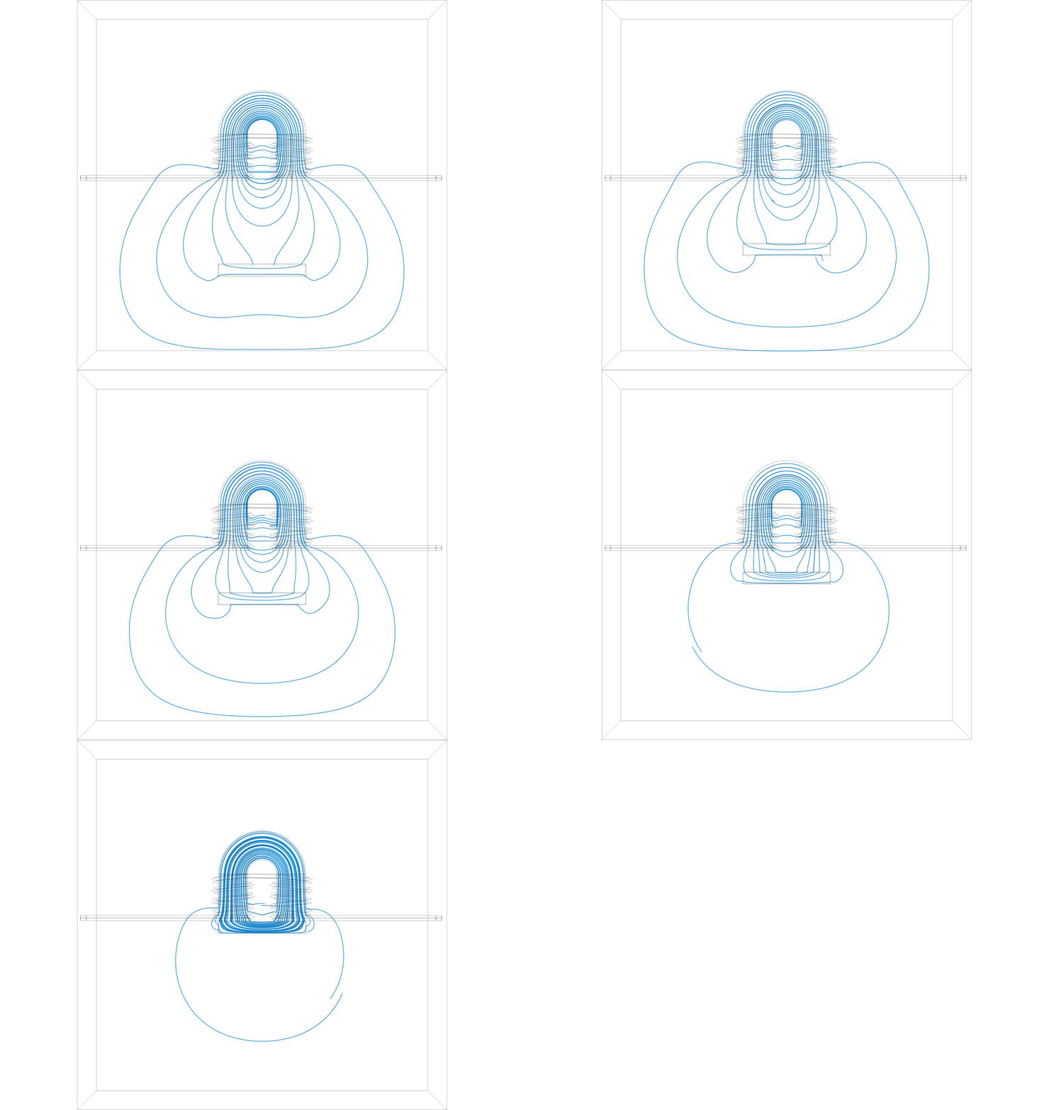
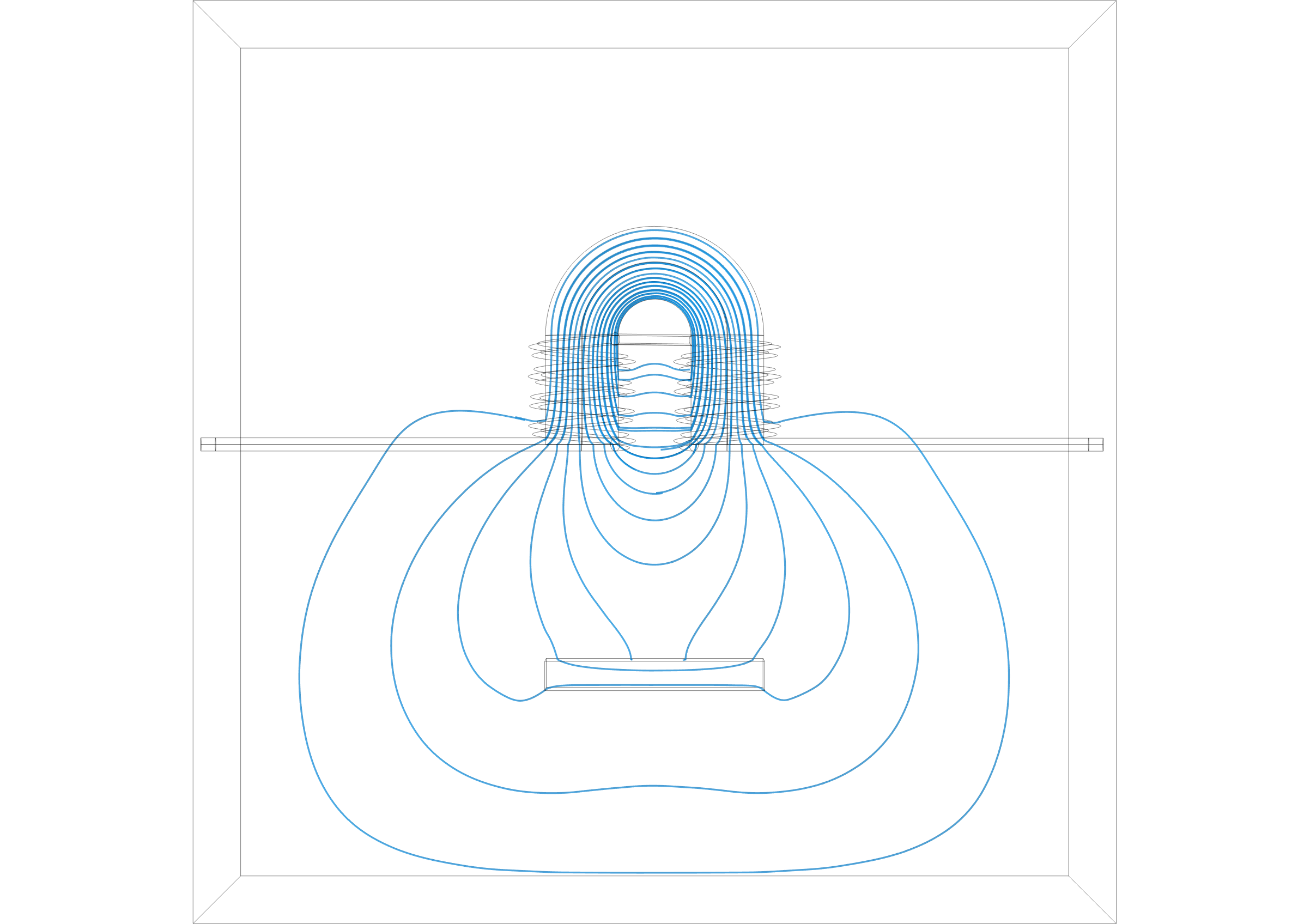
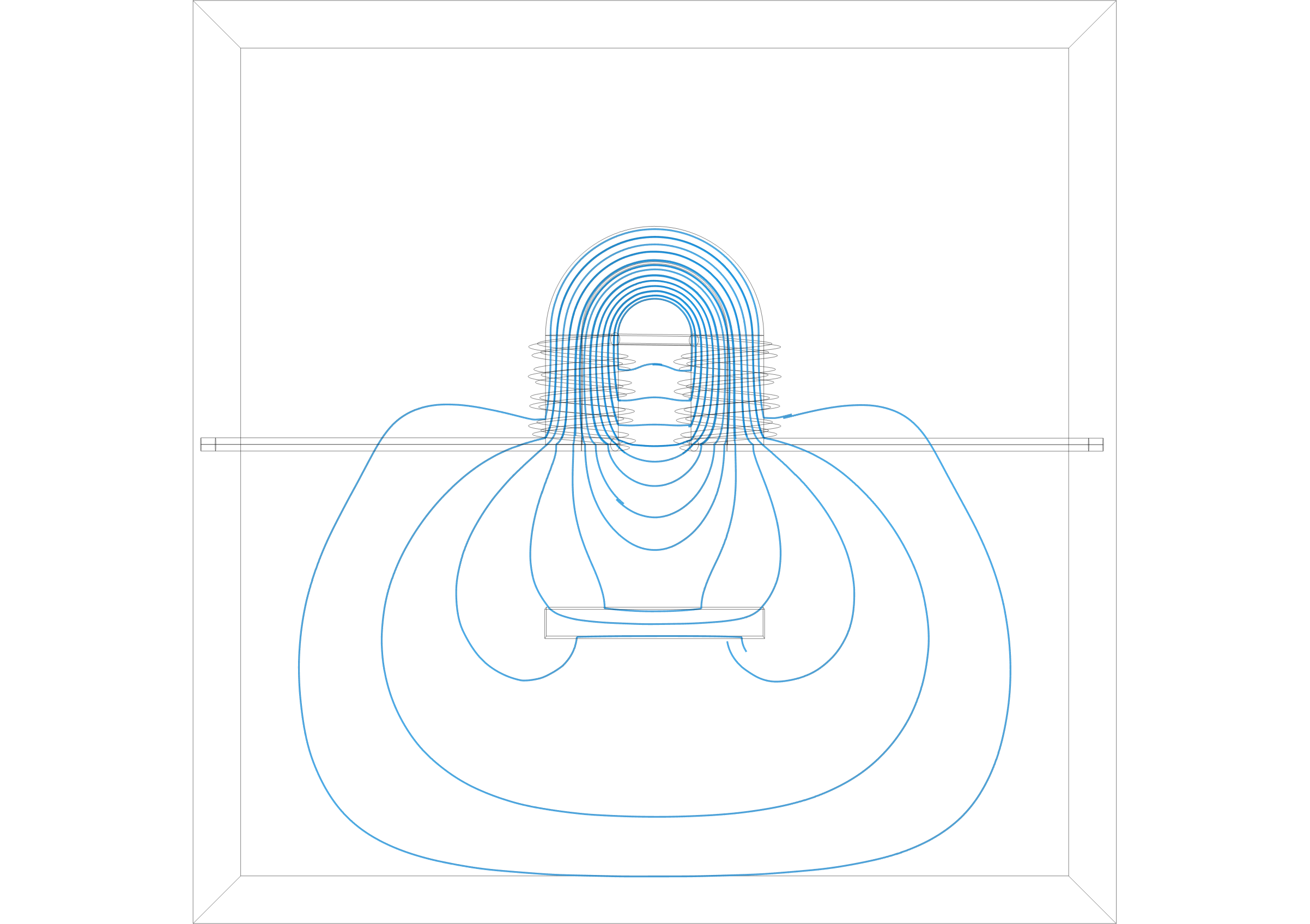
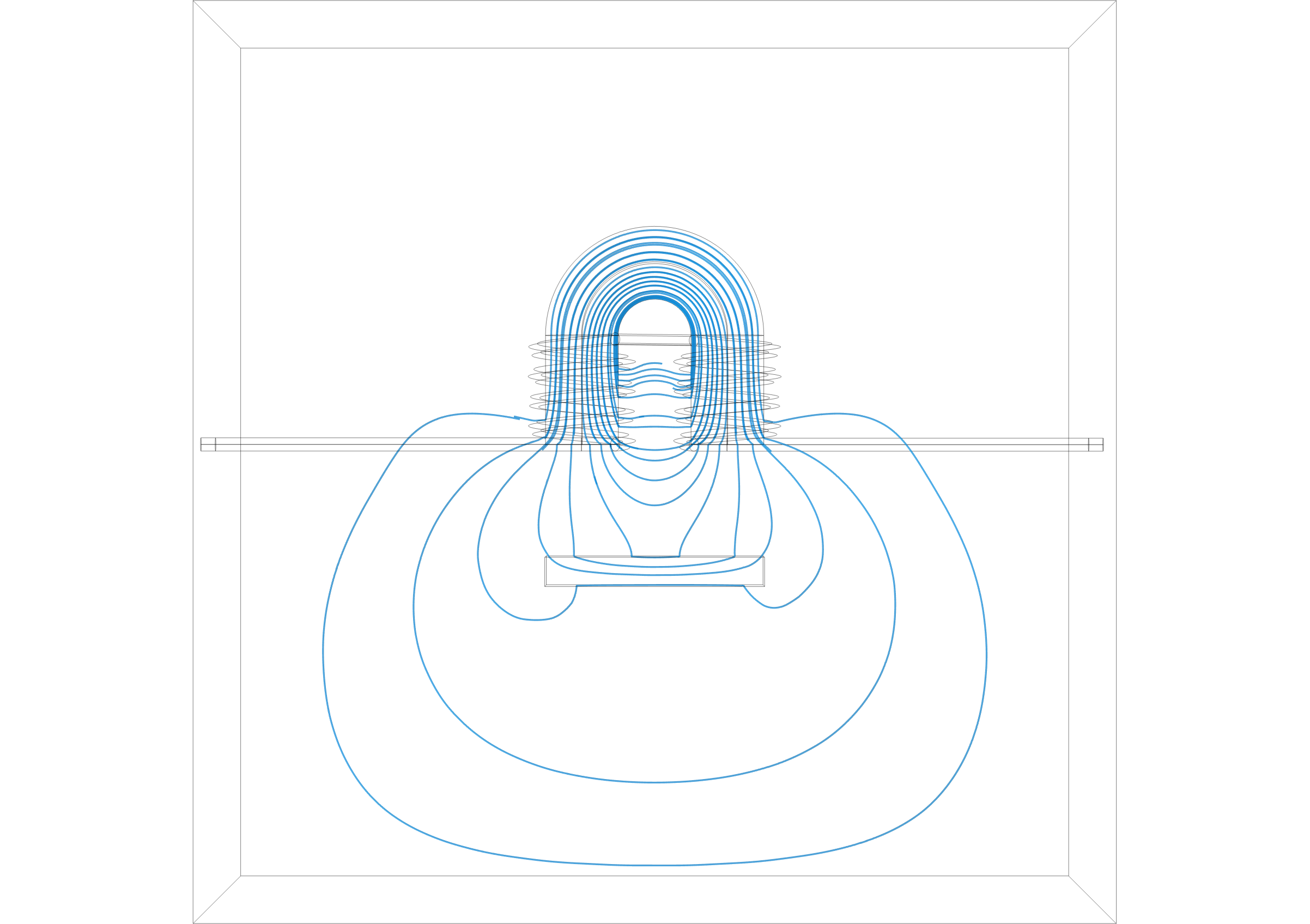
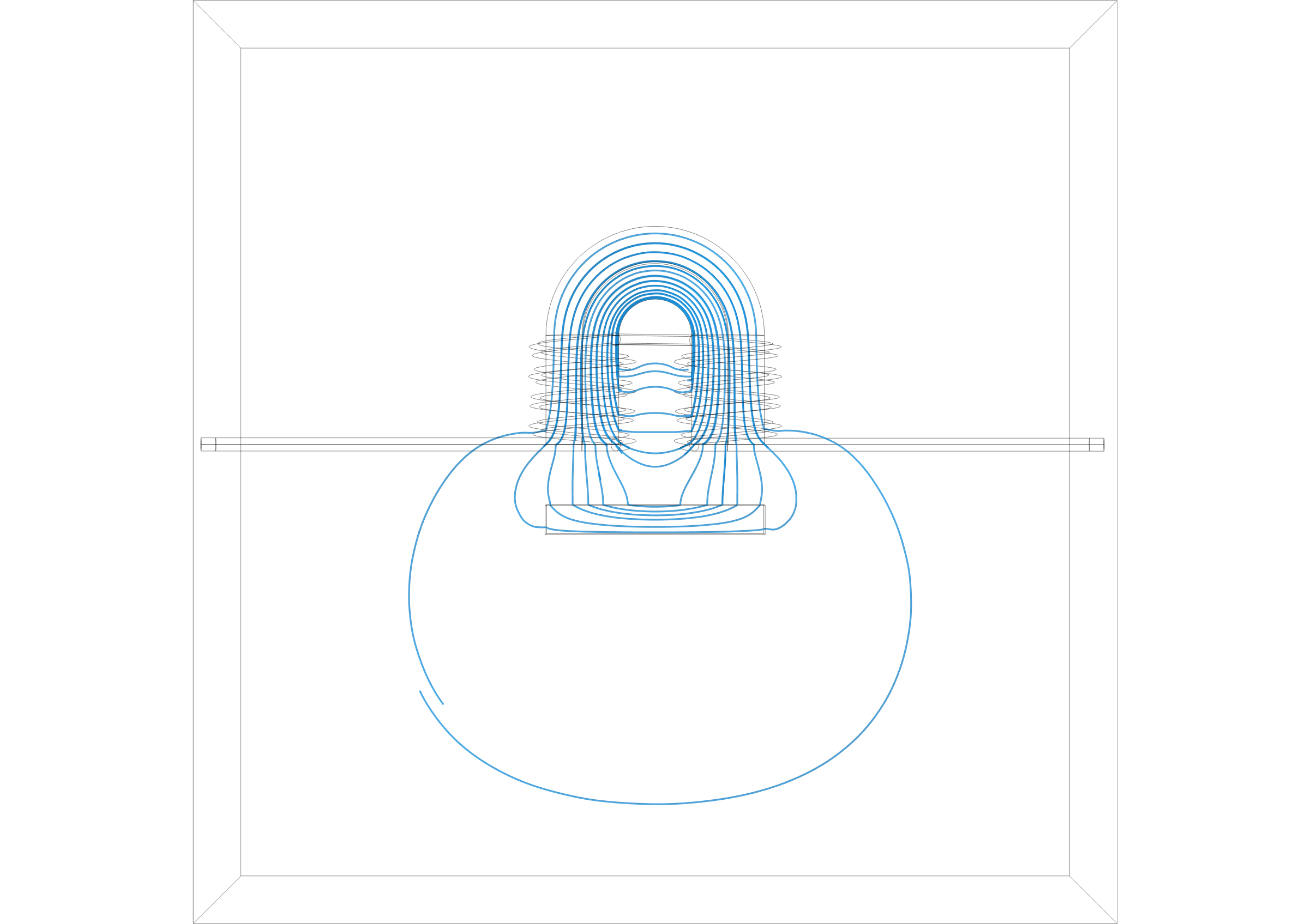
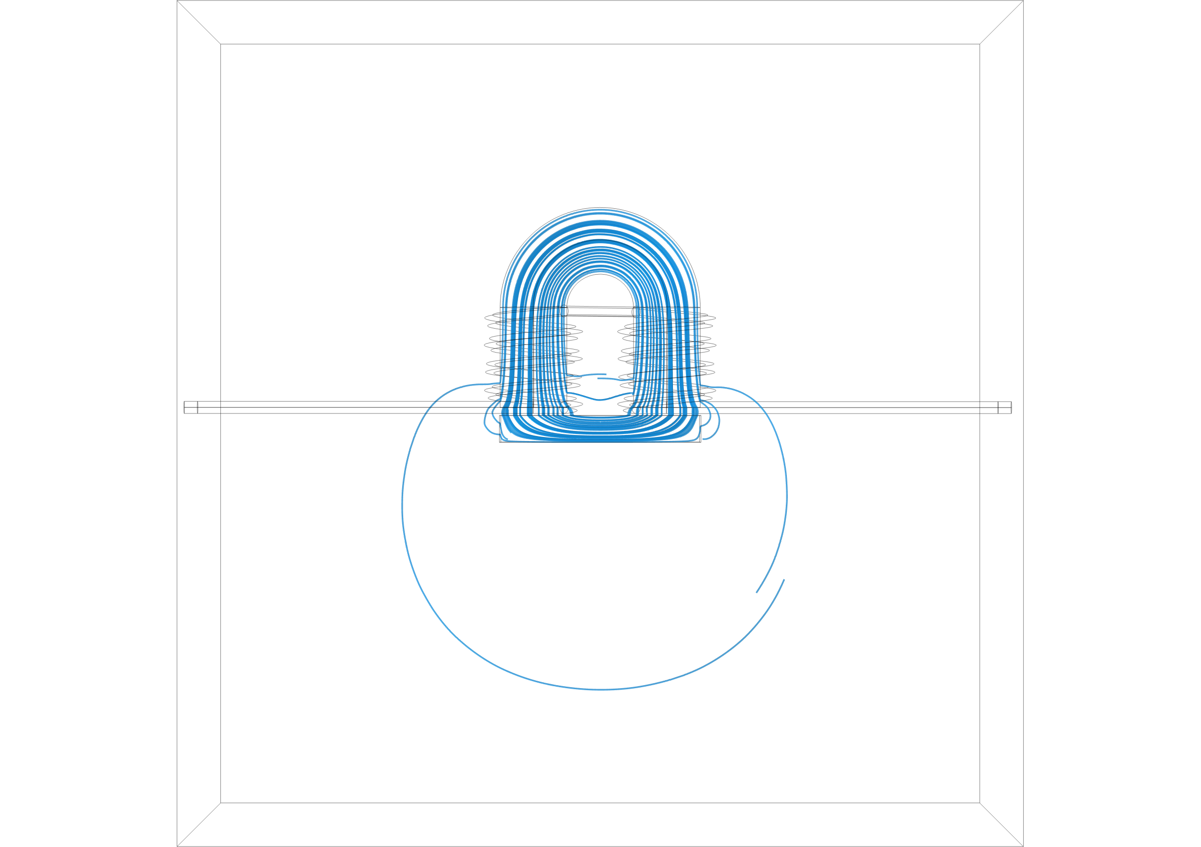
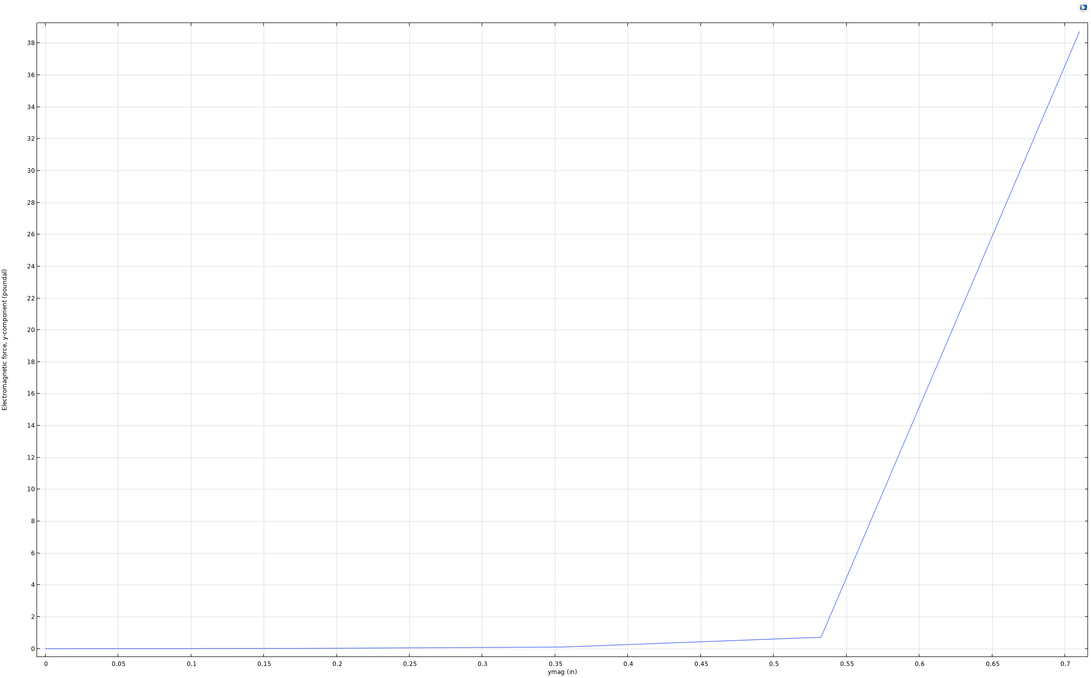
Magnetic Force on a Moving Bar – July 7 2026 – COMSOL File Version 6.3
Project 3: Henry’s Bell Ringer Experiment
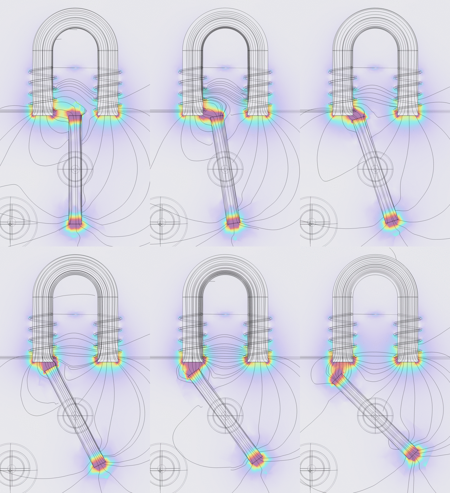
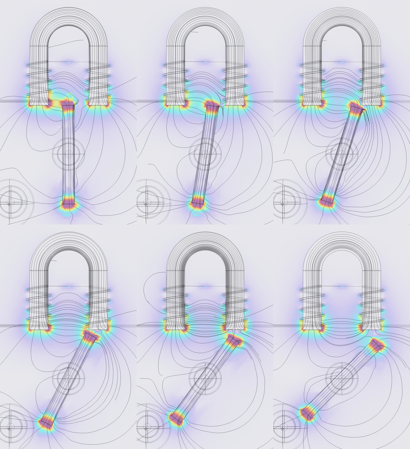
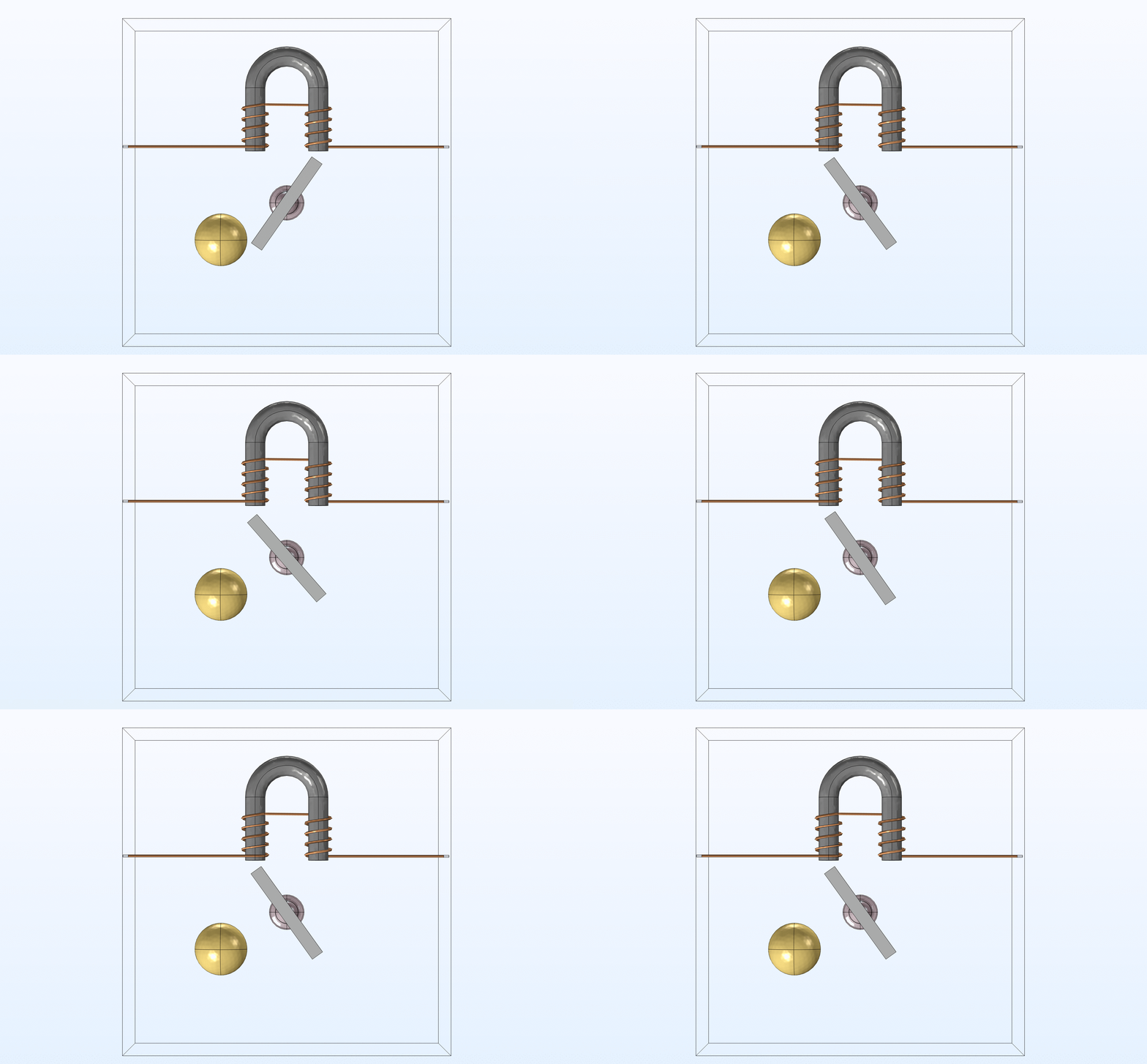
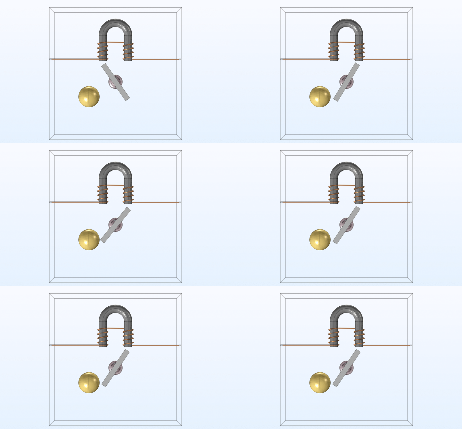
This project aimed to model Joseph Henry’s bell ringer experiment. The exact specifications for the horseshoe electromagnet were taken from Henry’s documentation while the bell, permanent bar magnet, and pivot were constructed with estimated dimensions from models online. The permanent magnet has the north pole assigned to the top of the bar and the south pole to the bottom. The model simulates the rotation of a bar magnet as the direction of current flips from towards the right to towards the left, and in turn switching the location of the electromagnet’s north and south poles. In each case, the permanent magnet swings to the south pole of the electromagnet.
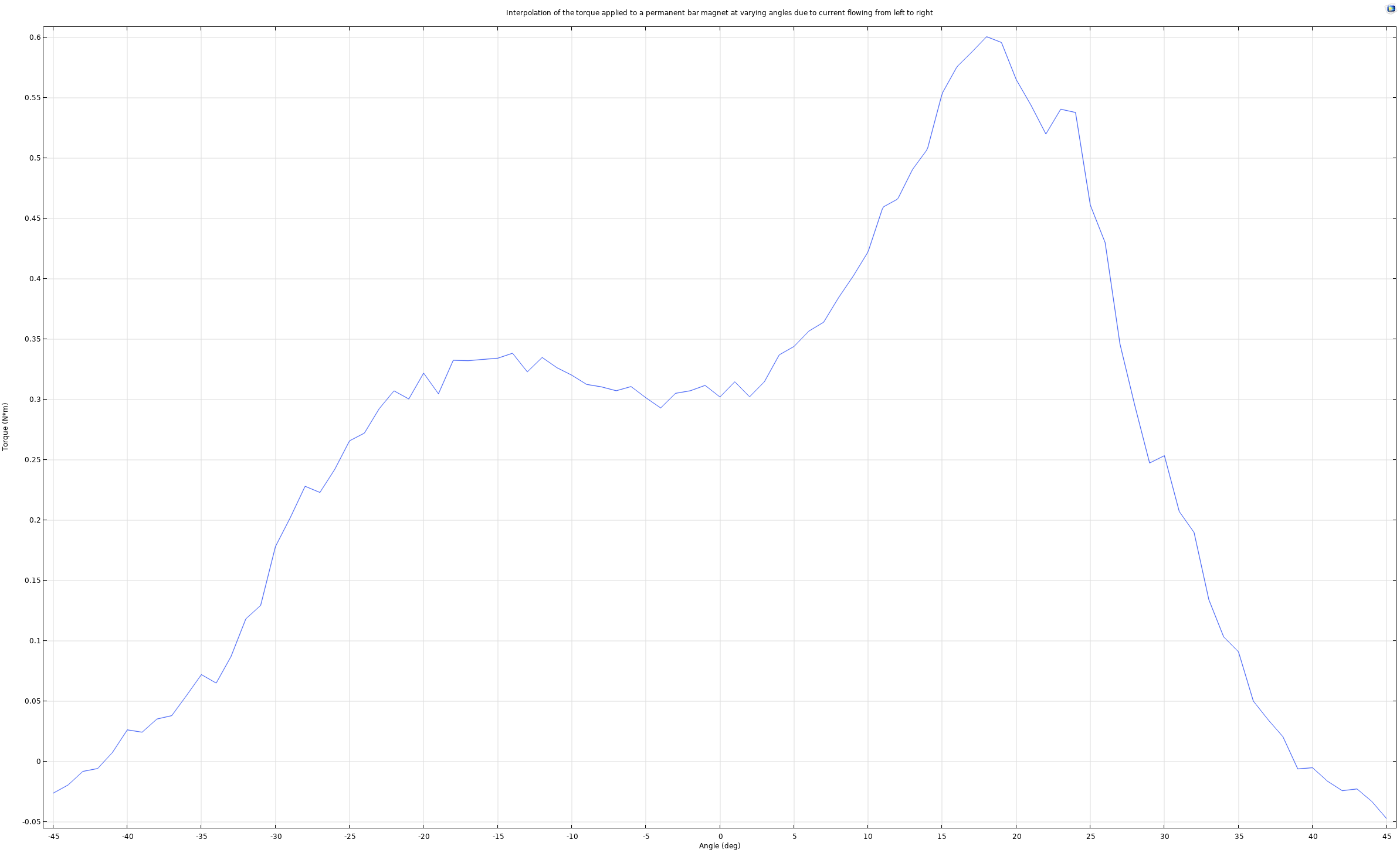
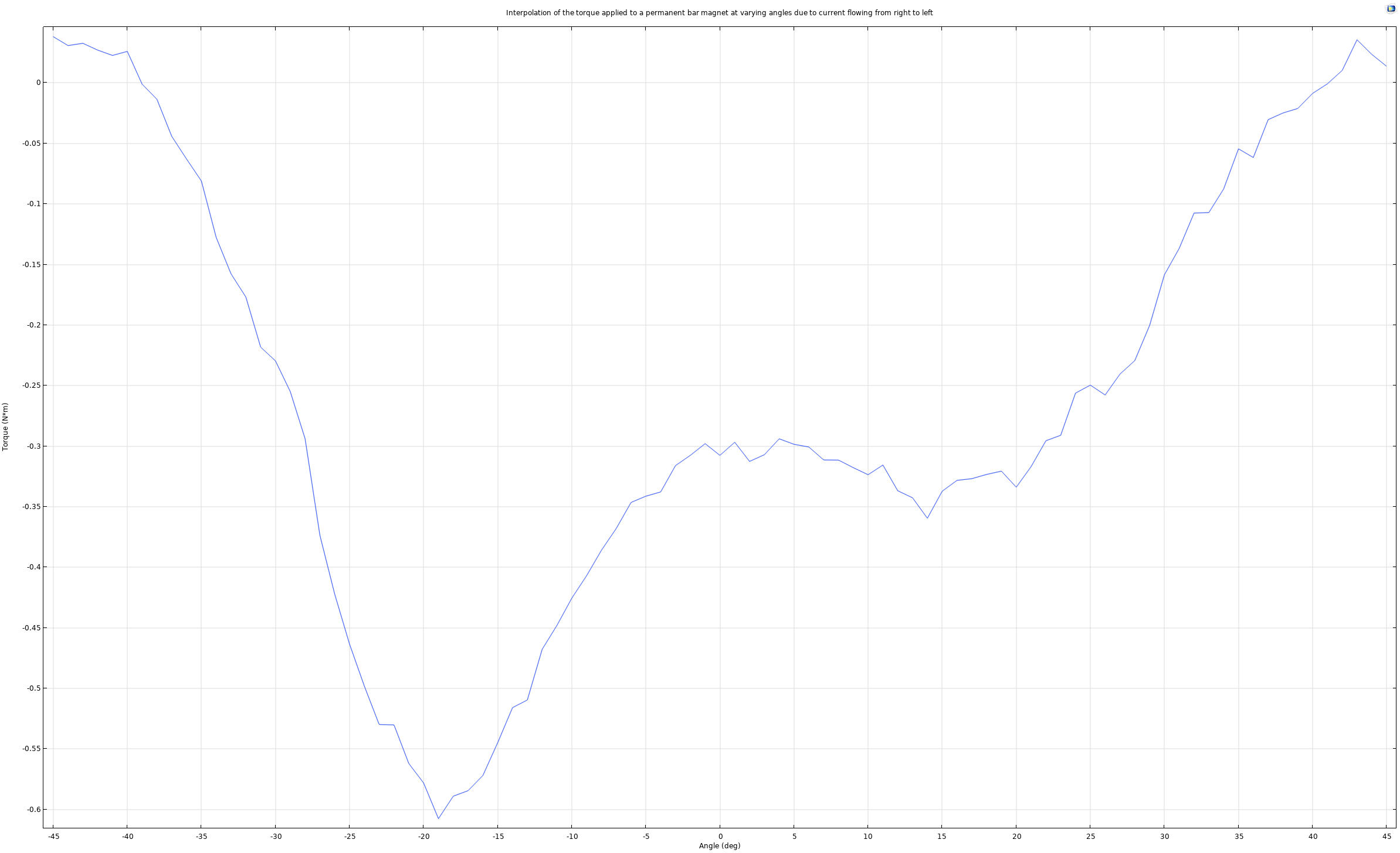
These simulations were constructed by coupling the Magnetic Fields, with currents package with the Multibody Dynamics package. The electromagnetic torque over a range of angles was calculated first, and those values were then used in a new study to apply a “moment” and induce angular rotation of the bar. When the current was reversed, I re-ran the study to find new magnetic torque values at the same range of angles. In order to have the bar start where it might in a continuous study, I set the initial value for the bars rotation in the right-to-left current study to be equal to the final angle of the left-to-right current study. After assigning the proper physics, the field lines shown were adjusted to better simulate the ideal diagrams in textbooks.
Project 4: Albany Magnet
This project aimed to simulate the lifting force of the Albany Magnet. The specifications for the magnet, including the number of coils, diameter of the copper wire, height of magnet, radius of iron core, and current through each coil, were directly lifted from “The Innovators” by David Billington. The total volume of the weight lifted was estimated from diagrams within the book and photographs online. Applying a force calculation to a cast iron bar beneath the electromagnet and calculating for the total value using the Pythagorean theorem gives a total force value of 750.59N. This value should be verified with further experimentation.
Raw and final calculated electromagnetic force values: albanyliftforce