String Oscillograph

Figure 1 String Oscillograph (Front View).

String Oscillogragh, first offered by General Radio in 1928, is a device that enables one to observe waveform of an electrical current in real time. This is accomplished by the following implementations. A very fine tungsten wire is positioned in a magnetic field supplied by a permanent magnet. When an electrical current flows through the wire, the wire will get deflected where the displacement of deflection is proportional to the amplitude of applied current. The string, being suspended in a beam of a powerful lamp, will then cast a shadow of itself upon an arc screen. Before the shadow strikes the screen, it will get reflected from an octagonal non-synchronous mirror, which rotates about an axis parallel to the line of string’s vibration, and be given an additional displacement that is proportional to time. As a result, string oscillograph converts waveform of electrical current into mechanical vibration, which is represented by spots of shadows well spread over the screen, eventually reproducing the waveform of the current which can be easily observed and studied.

For full description, please refer to the file attached below.

Size: 903.2K bytes Modified2 July 2014, 11:59
Size: 660.9K bytes Modified30 June 2014, 15:39
Size: 120.4K bytes Modified30 June 2014, 15:41
_________________________________________________

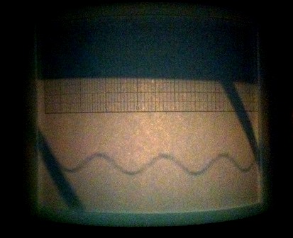
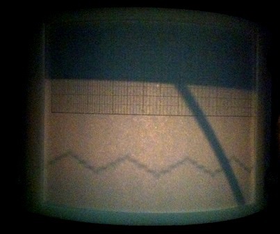
Pictures of Different Waveforms Displayed

Figure 2 Sine Wave.
Figure 3 Triangle Wave.
Figure 4 Square Wave.

_________________________________________________
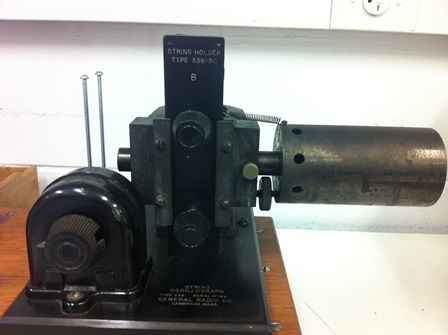
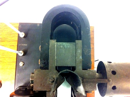
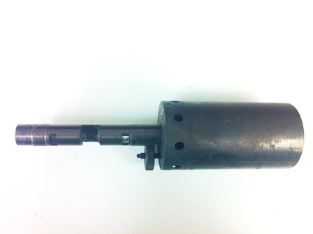
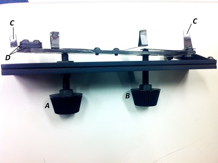
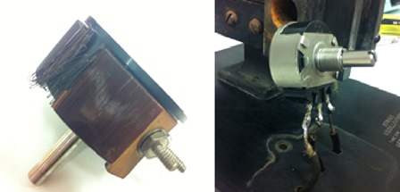
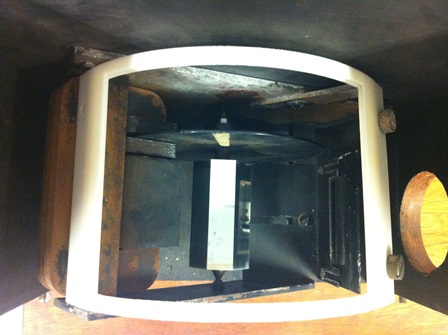
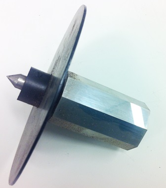
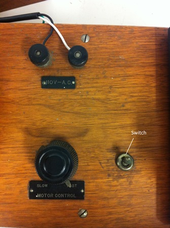
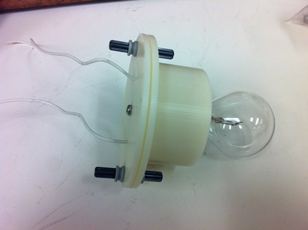
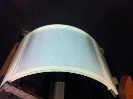
Pictures of String Oscillograph

Figure 5 Galvanometer Unit. It includes a pair of permanent horseshoe magnets, two terminals for AC current input, light source (not shown), projection lens, condenser, a string holder (contains a piece of wire) and a potentiometer.
Figure 6 Arrangment of a pair of permanent horseshoe magnets.
Figure 7 Magnification of the gap reserved for string’s oscillation (front view).
Figure 8 Magnification of the gap reserved for string’s oscillation (top view).
Figure 9 Projection lens and condenser.
Figure 10 String holder (front view). A: Knob for adjusting the overall position of the string. B: Knob for adjusting the tension on the string. C: Contacts between the holder and the string. D: Two layers of insulators.
Figure 11 String holder (top view). E: Contacts between the holder and potentiometer.
Figure 12 Potentiometers. The original potentiometer (left) with 180 ohms was broken and has been replaced by a new one (right) with 250 ohms.
Figure 13 Connections and schematic of the potentiometer.
Figure 14 Viewing box (front view). It contains a rotating octagonal mirror driven by a shaded-pole motor, a piece of cylindrical glass and a screen holder holding a piece of translucent paper screen (not shown).
Figure 15 Viewing box (top view).
Figure 16 Octagonal mirror.
Figure 17 Illustration of the shaded-pole Motor. A: Permanent magnet. B: Solenoid wound on the magnet. C: Terminals connected to the variac (not shown). D: Shaded-poles (winding wires not shown). E: Aluminum plate. F: Shaft holding the plate and the octagonal mirror (not shown).
Figure 18 Control board on the base.
Figure 19 Variac for motor’s speed control and transformer for light source.
Figure 20 Condenser.
Figure 21 Light source and 3D-printed lamp holder.
Figure 22 3D-printed screen holder.