Henry Motor – Letter to Jacob Green
See Littman and Stern, Am. J. Phys. 79, 172–181; 2011 – link below
AJPpaper.pdf
ON A RECIPROCATING MOTION PRODUCED BY MAGNETIC ATTRACTION AND REPULSION.
(Silliman’s American Journal of Science, July, 1831, vol. XX, pp. 340-343.)
To the Editor:
• Sir :—I have lately succeeded in producing motion in a little machine by a power, which, I believe, has never before been applied in mechanics—by magnetic attraction and repulsion.
Not much importance, however, is attached to the invention, since the article, in its present state, can only be considered a philosophical toy; although, in the progress of discovery and invention, it is not impossible that the same principle, or some modification of it on a more extended scale, may hereafter be applied to some useful purpose. But without reference to its practical utility, and only viewed as a new effect produced by one of the most mysterious agents of nature, you will not, perhaps, think the following account of it unworthy of a place in the Journal of Science.
It is well known that an attractive or repulsive force is exerted between two magnets, according as poles of different names, or poles of the same name, are presented to each other.
In order to understand how this principle can be applied to produce a reciprocating motion, let us suppose a bar magnet to be supported horizontally on an axis passing through the centre of gravity, in precisely the same manner as a dipping needle is poised; and suppose two other magnets to be placed perpendicularly, one under each pole of the horizontal magnet, and a little below it, with their north poles uppermost; then it is evident that the south pole of the horizontal magnet will be attracted by the north pole of one of the perpendicular magnets, and its north pole repelled by the north pole of the other: in this state it will remain at rest, but if, by any means, we reverse the polarity of the horizontal magnet, its position will be changed and the extremity, which was before attracted, will now be repelled; if the polarity be again reversed, the position will again be changed, and so on indefinitely: to produce, therefore, a continued vibration, it is only necessary to introduce, into this arrangement, some means by which the polarity of the horizontal magnet can be instantaneously changed, and that too by a cause which shall be put in operation by the motion of the magnet itself; how this can be effected, will not be difficult to conceive, when I mention that instead of a permanent steel magnet in the moveable part of the apparatus, a soft iron galvanic magnet is used.*
The change of polarity is produced simply by soldering to the extremities of the wires which surround the galvanic magnet, two small galvanic batteries in such a manner that the vibrations of the magnet itself may immerse these alternately into vessels of diluted acid; care being taken that the batteries are so attached that the current of galvanism from each shall pass around the magnet in an opposite direction.
Instead of soldering the batteries to the ends of the wires, and thus causing them at each vibration to be lifted from the acid by the power of the machine, they may be permanently fixed in the vessels, and the galvanic communication formed by the amalgamated ends of the wires dipping into cups of mercury.
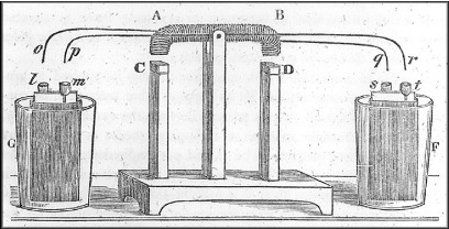
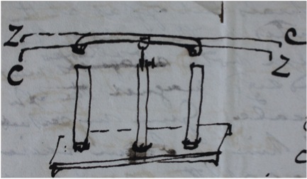
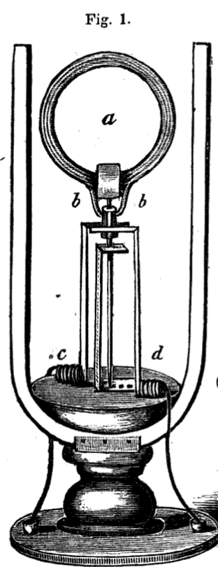
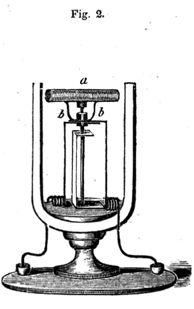
The whole will be more readily understood by a reference to the annexed drawing: a b is the horizontal magnet, about seven inches long, and movable on an axis at the centre: its two extremities when placed in a horizontal line, are about one inch from the north poles of the upright magnets c and d. g and f are two large tumblers containing diluted acid, in each of which is immersed a plate of zinc surrounded with copper. l, m, s, t, are four brass thimbles soldered to the zinc and copper of the batteries and filled with mercury.
The galvanic magnet ab is wound with three strands of copper bell-wire, each is about twenty-five feet long; the similar ends of these are twisted together so as to form two stiff wires, which project beyond the extremity b, and dip into the thimbles s, t.
To the wires q, r, two other wires are soldered so as to project in an opposite direction, and dip into the thimbles l, m. The wires of the galvanic magnet have thus, as it were, four projecting ends; and by inspecting the figure it will be seen that the extremity p, which dips into the cup m attached to the copper of the battery in g corresponds to the extremity r connecting with the zinc in f.
When the batteries are in action, if the end b is depressed until q, r dips into the cups s, t, ab instantly becomes a powerful magnet, having its north pole at b; this of course is repelled by the north pole d, while at the same time it is attracted by c, the position is consequently changed, and o, p comes in contact with the mercury in I, m; as soon as the communication is formed, the poles arc reversed, and the position again changed. If the tumblers be filled with strong diluted acid, the motion is at first very rapid and powerful, but it soon almost entirely ceases. By partially filling the tumblers with weak acid, and occasionally adding a small quantity of fresh acid, a uniform motion, at the rate of seventy-five vibrations in a minute, has been kept up for more than an hour: with a large battery and very weak acid, the motion might be continued for an indefinite length of time.
The motion, here described, is entirely distinct from that produced by the electro-magnetic combination of wires and magnets; it results directly from the mechanical action of ordinary magnetism: galvanism being only introduced for the purpose of changing the poles.
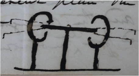
My friend, Prof. Green, of Philadelphia, to whom I first exhibited this machine in motion, recommended the substitution of galvanic magnets for the two perpendicular steel ones. If an article of this kind was to be constructed on a large scale, this would undoubtedly be the better plan, as magnets of that kind can be made of any required power; but for a small apparatus, intended merely to exhibit the motion, the plan here described is perhaps the most convenient.
Sturgeon’s History of Electric Motor (1839)
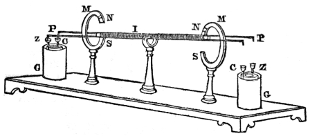
Henry’s 1835 Motor
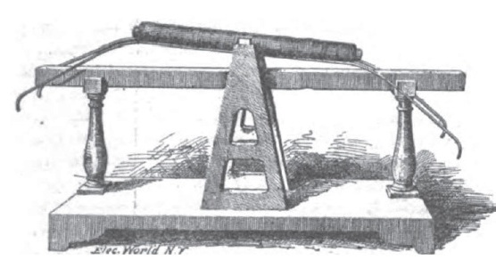
This image is from an article by the curator of electrical instruments of the Smithsonian. The image is of Joseph Henry’s electromagnetic motor that was placed on display in 1891 at an exhibition in honor of the 100th anniversary of the US Patent Office. The image is of a motor that we discovered was incorrectly pieced together after Joseph Henry’s death in 1878. Instead of a single horizontal bar magnet as shown, the motor should have be displayed with two C-shaped magnets as it appears at the top of this webpage. Click on the image to view the original article in the Electrical Engineer.
Francis Watkins – 1838 article on Electric Motors
Watkin’s (Smithsonian Curator) Article – 1891
1822-M-Faraday-homopolar-motor.pdf
Electric-Toy-Making-for-Amateurs.pdf
1975-Electric-Motor-PTechReview-35-077
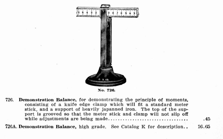
from Catalog M Central Scientific Company
Charles-Page-Obituary-Silliman-1869
Charles-Pages_The_American_Polytechnic_Journal
Davenport-motor-Journal-of-Franklin-Institute-1837