REMEMBER TO ALWAYS SELECT YOUR WORKING DIRECTORY! (this will make all of your files easy to find, and you will thank yourself later)
 1. Create your part.
2. Open a new Creo file, select Manufacturing —-> Mold cavity.
3. Select “Reference Model” at the top, and import your part file. Click “OK” twice.
4. Select “Coordinate System” in the Datum section of the top toolbar and set a new coordinate system in the center. Select the original coordinate system as a reference, and offset the dimensions to your liking.

5. Select “Workpiece” at the top. A menu will pop up on the side, and your model will already be selected. Next, it tells you to select a Mold Origin. Select your new coordinate system from the left menu or from the actual diagram. Click “Preview” to preview your mold. If you want your mold to be a specific size, you can adjust it under the “Offsets” section in the right menu.
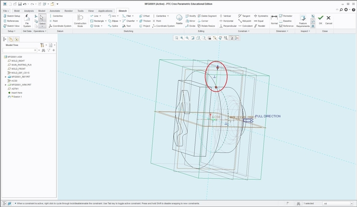
6. Creating runners. Go to View —> Display Style —> Hidden Line. Now you can see the outlines of your part and your mold. Sketch the path that you want your runner to follow using the Sketch tool, and make sure it connects the outside of the mold to the inside object. The sketching plane that you choose will be the plane on which the runner will open out to the mold surface.
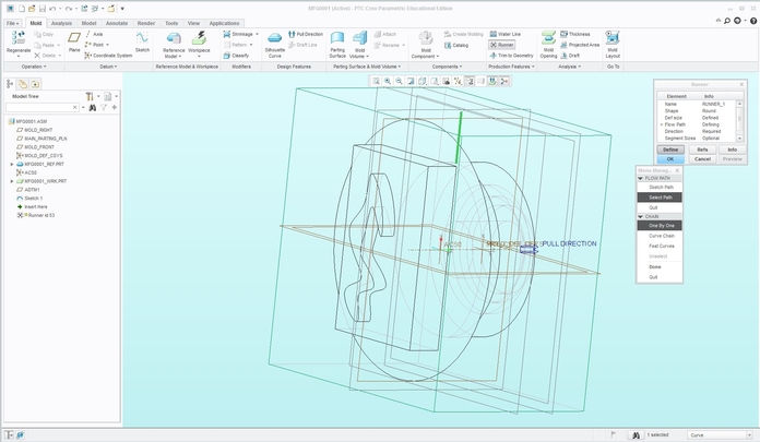
Then, select “Runner” under Production Features, and the pop up menu on the right will guide you through the process. Now you can choose the shape and size of your runner. When it gets to “Flow Path” in the menu, choose “Select Path” and then choose your previous sketch. Click “Done”. Then a window titled “Intersected Components” should pop up. Simply move your mouse over your mold in the window and it should be highlighted. Select the mold as the component and click OK. Finally click the blue OK to finish the process and your runner should appear. If you can an error, it may be because your shape or size isn’t compatible with the mold.

7. Create a parting surface. Go to “Parting Surface” —> “Sketch”. Choose the plane on the mold on which you want to create the parting line for your mold. Sketch any line that goes from one end to the other. Complete the sketch, then “Extrude” the line to the opposite surface. Click on the rectangular symbol to the left of the depth length and choose “Extrude to selected point, curve, surface, etc.”, then select the opposite surface of the mold on which you want to extrude your line to.

Your parting surface should come out something like this:
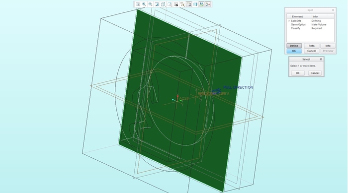
8. Click the arrow under “Mold Volume” and select “Volume Split”. A menu will pop up in the top right corner, and “Two Volumes” will already be selected. This will split your mold into 2 separate parts, click “DONE” to proceed. Select the parting surface you created as your “Split Srfs”, click the “OK” in the small dialog box, make sure everything in the menu is “Defined”, then click the blue “OK”.

Creo will then highlight each of the two parts and ask you to name each part.

You should see this in the menu on the left:

9. Now, you’d probably want to edit these 2 halves as separate part files in Creo. Converting them is an easy process. After doing the “Volume Split” above, select “Mold Component” at the top and select both of the parts you just named to export them as separate files.

You should now see the 2 parts on the left menu. You can right click on them and select “Open” to open the individual part in a new Creo window, allowing you to openly edit such as adding pegs/holes, etc.
10. Now you have successfully created your mold! If you selected your working directory in the beginning, you can now go to that location and see all of the separate part files and print them out if necessary.
Contact jamescc@princeton.edu with any questions.