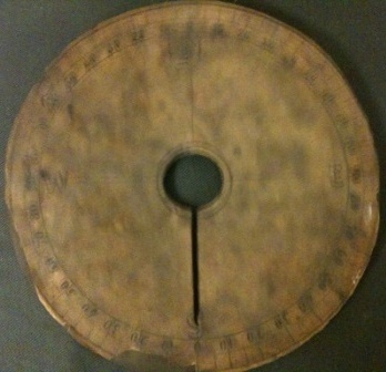
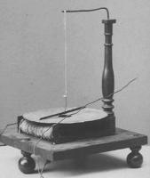
This graduated disk belongs on top of the Henry galvanometer, as depicted in the picture given by Mary Henry. The numbers read from 0 to 90, giving the degrees along each quarter circle, 0 being the top and bottom of the disk. The letters N, S, E, W give the four cardinal directions, marking the original N-S position of the needle.
When current is passed through the galvanometer coil, the needle deflects. This follows from Oersted’s discovery that a magnetic needle rotates to be tangential to a current-carrying wire. The disk serves to measure the angle of deflection, and thus the strength of the current. However, the fallacy of these early galvanometers is that while they served well in indicating the presence of a current, they could not give accurate quantitative measurements of it.
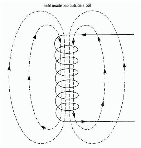
As can be seen in the diagram above, when the needle deflects, it moves out of the plane of the coil, and the position of each turn of the wire changes in relation to the needle. This causes the force of the current upon the needle to decrease, meaning that the strength of the current running through the coil is not proportional to the angle of deviation (although it is approximately so under 20 degrees). Thus, scientists of this time period recorded that as the amount of current increased, the additional deflection observed would decrease.
However, you can convert one of these early galvanometers into a sine galvanometer simply by placing it upon a rotating disk. Then, you can quantify the amount of current passing through the coil. Here is the method for doing so.