Compiled by Tanishk Shanker – tanishk@princeton.edu
Preambulatory
This page is designed for students using CNC Machinery in the EPICS Lab (End of H-Block in the Equad). In the room we have a Carvey and X-Carve connected to an iMac that dual boots Windows 10 and Mac OS Sierra. All required software and drivers needed in this page are already installed on these machines, but if you wish to use your own computer, you will have to install them yourself. We get most of them for free as part of the Engineering Student Software package.
Contents:
2. X-Carve Large (750mm x 750mm) CNC Mill
3. Easel Web-based 2.5D Modeling software
4. Fusion 3D Modeling software with official post processor
5. Creo 3D Modeling software with .NC exporting capability
6. Pocket NC 5-axis Desktop CNC Mill
Carvey Desktop CNC mill
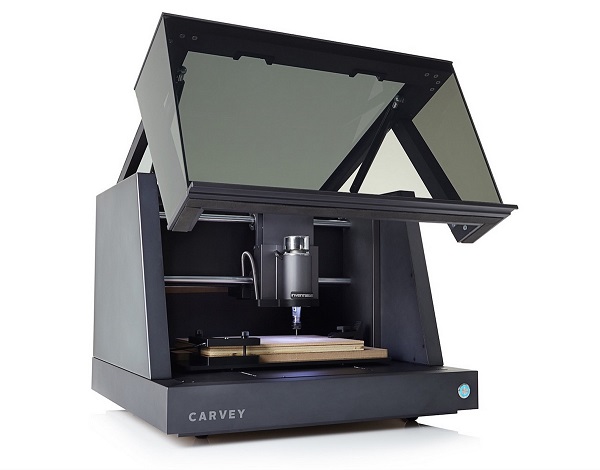
The Carvey is the newest desktop-sized, computer-controlled milling machine from Inventables.
With a carving volume of 11.6 x 8 x 2.75 inches (29 x 20 x 7 cm), the Carvey can cut wood, acrylic, plastics, some soft metals, foam, wax, and even carve PCBs. The machine needs to be connected to a computer running the Easel web application found at http://easel.inventables.com/.
X-Carve
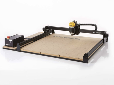
The X-Carve is a larger sized version of the Carvey with a few differences.
The belts now have simple plastic fittings, there are no eccentric nuts and use eccentric spacers with locking hardware. The pulleys are permanently mounted and there is no crimping and soldering plugs. Finally, the drag chain has 2x the area and has openable links in case you want to make changes.
The carve area is X-axis: 750mm, Y-axis: 750mm, Z-axis: 65mm. And uses easel to import designs.
Recommended rates are X/Y Axis: 800 mm/min and Z Axis: 500 mm/min.
Easel
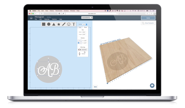
Easel is the all-in-one software solution for 3D carving machines. Designed by Inventables, Easel is the easiest way to get started in the world of 3D carving.
Easel is a wysiwyg web-software for the CNC machines. It automatically sets the toolpaths based on the design that you make. You can design in 2D, preview it in 3D, in real-time. Make a design from scratch or import SVGs you’ve made with vector design software.
From the blank canvas in easel, be first you want to specify the x, y and z dimensions of your material that you will be working in. Once this is done, you can add elements to the design. These can be the simple shapes outlined at the top, icons, images (svg format) or text. Each element can vary in size and cut depth, which you specify in the vertical toolbar to the right.
Then you use the cut menu on each element to determine the design of fill/outline. The 3D preview makes this easy to visualize. Designs can be make complex by combining multiple elements together. Easel will always preview the lowest cut depth at every point of the shape, so there is no need to worry about overlapping depths and shapes. This redundancy will be removed by the software. There will be a new toolbar if you select multiple shapes at the top, which will let you align multiple shapes too.
Stacking design elements and setting different depths gives your project complexity. Darker shades indicate deeper carves, and lighter shades indicate little or no carving. This form of layering is known as 2.5D, and will allow the depth to vary along your shape. (For true 3D, see the G-code tutorial below.)
Finally, pick the material and click carve, it’s that easy.
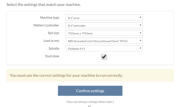
Instructions for how to set up the Carvey and X-Carve in the lab are attached below.
X-Carve Calibration
If experiencing problems with the X-Carve including incorrectly sized cuts or cuts that are too deep, it is important to make sure that the X-Carve is calibrated. This is a fairly simple process, once one understands the tools that are used to calibrate it. To calibrate the X-Carve we are going to be using a program called Universal G-code Sender to edit the settings of the firmware that the X-Carve runs on known as Grbl. The settings we will change will affect how many steps the X-carve’s motors make to travel a certain distance. A full guide on Calibration as well as a guide to using Grbl will be linked below.
Autodesk Fusion
3D CAD, CAM, and CAE tool that connects your entire product development process in a single cloud-based platform that works on both Mac and PC
To use Autodesk Fusion, we must import a post-processor developed by Inventables to convert a design into G-code. This can then be imported into easel for manufacturing.
The post-processor is available here for windows. For mac, you must follow this tutorial to install the post-processor. On the machine connected to the Carvey and X-Carve, these are already installed.
Then, in Easel In Fusion 360, open the Post Process dialog under CAM and set the configuration folder to a folder containing the downloaded Easel.cps. Next, select Easel.cps as the post configuration.
Note, toolpaths must be absolutely positioned inside the work area, away from the clamps. If you are using multiple bits, you also must export only one tool per file.
Easel Post Processor for Fusion
Creo
Design software supporting product design for discrete manufacturers
This tutorial will teach you how to use creo and export as .NC. This can then be imported into easel and used to carve on the CNC machines.
Note: This will ONLY work in Windows 8 or later, for Mac OS, you must use Autodesk fusion.
All the full creo tutorials are attached below, so if you want to learn from scratch you can, but if you already have a design or imported a .dwg, then you can use this to learn how to export and ensure the G-code is compatible with easel. If you have never used creo before then I would advise to follow the tutorials attached below (number 18 is for exporting) as they are more detailed and are accompanied with screenshots.
CREO works by producing a 3D solid model of components that can be exported to many other standard formats. Once you have a working directory set and have a model that you would like to export as G-code, you must know the following.
Every move of the cutter is linked to the machine coordinate system. This coordinate system is the zero point of the program. It needs to be placed in a specific direction and location on the part. If the part is a rectangle or has at least two square edges the coordinate system should be placed on this corner at the top surface. Doing this allows you to set the machine to a measurable spot (the edges and top).
FOR THE CARVEY THE ORIGIN IS THE BOTTOM LEFT OF THE MACHINE, FOR THE X-CARVE IT IS WHEREEVER THE DRILL BIT STARTS MILLING FROM. THUS, THSE SAME CODE CANNOT BE USED FOR BOTH MACHINES, THEY REQUIRE A DIFFERENT STARTING REFERENCE FRAME.
The milling machine has specific axes assigned. These are looking down from the top.
The X axis is left to right. Y axis is from front to back. Z axis is from the top of the part up.
In creo, these as a 1st Quadrant Cartesian coordinate system placed on your part.
The next item you will need to know is what cutter to use for the task and what feeds and speeds will be assigned. None of this is done for you, so you will need to choose these items. In order to do this you need to have a few bits of information such as; Material Type, area to be machined in order to choose the proper milling cutter, Spindle (cutter speed) and Feed rate (movement in inches per minute).
These all depend on the drill bit and cutting material.
1. Set up in manufacturing
Now you will need to set up in manufacturing. Create a new creo session and choosing manufacturing, with the subtype as NC assembly. In this session, choose the assemble reference model and pick the part that you designed. Then change the placement option from automatic to default. Next you need to create the work piece, the block of material you are making the piece from. To do this, click workpiece and pick placement then click the default coordinate system.
2. Create a volume for milling
A Mill Volume is the area that you want the milling cutter to use to machine the part features. This is down in the geometry tab, you click mill volume and extrude. Then go to the sketching tab and click offset, and loop, this should be applied to the outline of the shape that you want to mill. MAKE SURE YOU CLICK THE PART and not the working plane. Depending on the size of the bit, the value of this clearance will change. For a 3/16″ mill, the distance is .210. Next click trim on the Mill Volume tab and click accept. There may be other small adjustments that you will have to do depending on the complexity of the shape, refer to the tutorial 18 in the files below for a full list of them if this does not satisfy all of the milling volume set up.
3. Volume rough
Click the Mill tab, and pick the Roughing button. Choose the pulldown and choose Volume Roughing. Pick the pull down menu in the Tool Window and choose Edit Tools. Creating new tools is fairly easy; First you need to create what the maximum radius is in the corners. This usually sets the decision for the final finish paths. Name the tool “T1” and when completed filling out all of the information, pick “Apply”, and the tool will now be displayed in the window. You will notice the Tool Position is 1 and the Tool ID is T1.
Next click the reference tab and pick the parameters. You will have to enter a CUT_FEED, PLUNGE_FEED, STEP_OVER, MAX_STEP_DEPTH, CLEAR_DIST and SPINLE_SPEED.
There are many different values you can put and if you are unsure ask someone supervising the lab. One baseline is:
CUT_FEED: 25
PLUNGE_FEED: 5
STEP_OVER: 0.09375
MAX_STEP_DEPTH: 0.075
CLEAR_DIST: 0.1
SPINLE_SPEED: 5500
4. Volume Rough 2
Click the Volume Rough icon again and edit the tools as before. Then go to settings and change the settings to the Tool ID and click ID. Next click the parameters and click the copy from previous tab button. Now click the previous volume mill and scroll down until you see the step over and change this to half the end mill diameter, Then change the rough stock allowance to 0 and change the rough only to prof only using the pull down menu
5. Peck Starter Dilling
When drilling in the CNC and all machines you will need to starter drill the holes before drilling. The following is the procedure for starter drilling and drilling holes. Peck or deep is used so that the chip and coolant can get in and out of the holes. If standard drilling were used the drill could heat up stick and break or not drill straight.
To do this, click pecking and pick the references tab and details.
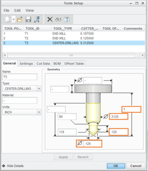
Move the available hole diameter. of .15 to the selected side of window. Next pick the details button. Change the End to Blind and fill in .10. Pick Edit Tools from the pull down menu, and create Tool 3 by picking the pull down menu from the tool window. Change the Name to T3.
The first tool for drilling we will be use is the starter drill, sometimes called center drill. Assign the proper T# and settings #. For this part the starter drill will be tool 3. Use the pull-down menu to choose center drilling (you will need to scroll down) Fill in the values as shown in the picture below and click apply.
6. Peck Drilling
Follow the same steps as in 5, and create a new tool with ID 4. Now in references and details leave the end as Auto. In parameters fill in the same values as in the previous tab and click accept.
For text engraving you will have to create a new tool and use an engraving setting. This can be seen on page 36 of tutorial 18 below.
7. Coding
After saving session pick the Manufacturing tab at the top of tool bar. Pick the Save a CL File button from the Output Tab. Choose the Save a CL File. Pick Operation and then OP010 (This is the only choice of operations for this part.) Pick File, MCD File, Compute CL, and then Done.
Name the operation, pick OK and wait for PP Option to appear, then pick Done. Now a list of machining processors will open, click the most valid one and hit Enter. A window will show time and warnings. The times shown for the mini mill are accurate but the other machines are wrong and will show warnings sometimes. They seem to be OK. Close info window and pick Done Output from the window on right.
Now we will show animation of entire manufacturing. Pick the Play Path button from the Validate Tab. Pick the Material removal. CL file
Choose your file from window and then Done.
Now you will have a .NC file that can be imported into easel for use with the Carvey and X-Carve.
Pocket NC
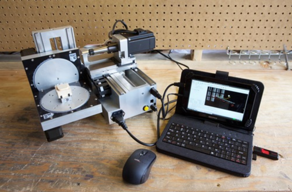
The Pocket NC is a 5-axis Tabletop CNC Mill. It is comprised of many large machined aluminum pieces and has real linear guides. It has a real spindle and housed a beagle bone black running linuxCNC. It can take straight G-code, but was developed with and uses Autodesk Fusion360 for the toolchain. This tutorial will show how to use Fusion360 with the PocketNC to mill an object.
The post processor for Fusion is included with the software and already installed on the computers in the EPICS Lab. If you are not using one of these machines then you will have to download and install if yourself from their website.
http://www.pocketnc.com/getting-started/
http://www.pocketnc.com/blog/2017/5/4/pocket-nc-cam-setup-video
For reference, the specs for axes and spindle are reproduced below:
X Axis
Max Speed: 40 ipm (inches per minute)
Resolution: 0.000125in
Backlash: 0.0005 in at tool base
Deflection at 5 pound load : 0.001 in at tool base
Max Travel: 4.5 in
Homing Repeatability: +/-0.0005 in
Repeatability: +/-0.002 in at 0% load
Y Axis
Max Speed: 40 ipm (inches per minute)
Resolution: 0.000125 in
Backlash : 0.0005 in at tool base
Deflection at 8 pound load : 0.001 in at tool base
Max Travel: 4.8 in
Homing Repeatability: +/-0.0005 in
Repeatability: +/-0.002 in at 0% load
Z Axis
Max Speed: 40 ipm (inches per minute)
Resolution: 0.000125in
Backlash at 18 pound load : 0.0005 in
Deflection at 18 pound load : 0.001 in
Max Travel: 3.3 in
Homing Repeatability: +/-0.0005 in
Repeatability: +/-0.002 in at 0% load
A Axis
Max Speed: 20 degrees/second
Resolution: 0.025 degrees
Backlash: 0.05 degrees
Deflection at 2 pound load : 0.001 in at table center
Max Travel: 100 degrees (90 degrees +/- 5 degrees)
Homing Repeatability: +/-0.05 degrees
Repeatability: +/-0.05 degrees at 0% load
B Axis
Max Speed: 40 degrees/second
Resolution: 0.025 degrees
Backlash: 0.05 degrees
Deflection at 2 pound load : 0.001 in at table center
Max Travel: continuous rotation
Homing Repeatability: +/-0.05 degrees
Repeatability: +/-0.05 degrees at 0% load
Spindle
Spindle Speed: 65-10,000 rpm
Power Output: 104 Watts
Spindle Motor: BLDC 3 Phase with Hall Feedback
Spindle Runout: 0.002in or better
Tool Change: Lever Type (no wrenches needed)
Tooling: 1/8in shank (collet for 2mm, 3mm, or 4mm can be purchased)