Ryan Yu | 8/12/25
The first step was to simulate the galvanic cell and determine the exact current flowing through the external wire, which I assume to be constant throughout the device’s operation. In COMSOL, I recreated the device within an electrolyte domain (35% sulfuric acid), with the submerged geometry modeled as empty space in solution.

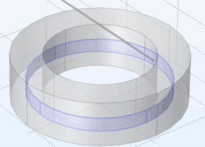
Physical & COMSOL constructions
The relevant geometry constructed for this problem was the electrodes (zinc and copper surfaces) and the electrolyte (sulfuric acid). I used COMSOL’s Secondary Current Distribution interface to model this system. The redox reactions at the electrodes are:
Zinc oxidation: Zn → Zn²⁺ + 2e⁻
Copper reduction: Cu²⁺ + 2e⁻ → Cu
I used standard equilibrium potentials for each electrode: −0.74 V for Zn and +0.34 V for Cu. This was done under an assumption that the reduced and oxidized species expressions are unchanged.

Nernst Equation; C(r) & C(o) are both 1, so the reference equilibrium potential is accurate.
To define electrode surface kinetics, I used the Anodic and Cathodic Tafel expressions, as the reactions only proceed in one direction (due to high overpotentials). I defined an anodic slope of 59 mV/decade, cathodic slope of -59mV/decade, and an exchange current density of 0.5 A/m² for both half-reactions. The electrolyte conductivity for 35% sulfuric acid is high (We conducted our experiment in a fume hood). I used 280 S/m, based on experimental data from the NIST.
The zinc and copper electrodes are electrically connected via an external copper wire that has the length of the copper arch and the resistive properties of copper. From this setup, COMSOL computed the resulting current through the wire:
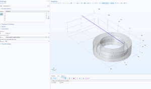

The current flowing through the wire is .52541 A. This both corroborates the measurement of .5 A observed in the physical experiment, and allows me to apply .52541 A as a constant current to the copper arch geometry in Step 2!