Tesla Pratt, 7/25/24 – Professor Littman
Objective: I will study Michael Faraday’s lab notebook and diaries, and recreate his experimental procedures with the unipolar electric generator. I will design a simulation in COMSOL multiphysics to compare with calculated and experimental results from my recreation. An analysis of both calculated, simulated, and experimental data, I look to confirm Faraday’s results with various configurations and tests with the homopolar generator.
In 1831, Faraday discovered electromagnetic induction by passing a magnet through coiled wire. He attached a galvanometer to the coil, and observed that moving his magnet through created a deflection in the needle. Curiously, this “induced current” in the coil could only be observed when there was relative motion between the two bodies. If both were held in close proximity but without movement, no deflection occurred. These experiments led Faraday to develop Faraday’s Law: E=-Nt, which states that E (in volts) is equal to the change in flux of the system, over change in time. In other words, as the magnetic flux/field changes in the system over a certain interval of time, electricity is produced.
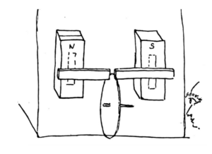
Faraday saw this as an opportunity to produce electricity in a new way, and created the first electric generator – the faraday unipolar generator. In a diary entry from October 1831, Faraday details the physical configuration of the generator, and draws a sketch:
Diary Entry OCT. 28, 1831: “99*. Made many expts. With a copper revolving plate about 12 inches in diameter and about ⅕ of inch thick, mounted on a brass axle. To concentrate the polar action two small magnets 6 or 7 inches long, about 1 inch wide and half an inch thick were put against the front of the large poles, transverse to them and with their flat sides against them, and the ends pushed forward until sufficiently near”(Faraday’s Diary VOL I, 381)
How Current is Induced in the Plate:
Faraday summarizes the effects of rotating the plate through a magnetic field in another diary entry from November 1831 explaining that “the rotating plate is merely another form of the simpler experiment of passing a piece of metal between the magnetic poles”. In both cases – disc and metal bar, currents of electricity are produced at right angles to the direction of motion (Eddy Currents) in the place where the magnetic poles cross the surface.
Model Replica: Using parts we had on-hand in the Princeton MAE lab, I designed a replica model of Faraday’s original experiment:
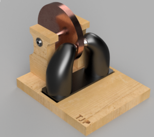
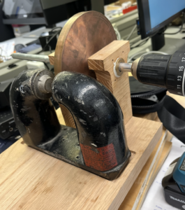
- Copper Disc: 6” diameter, ½” thick
- Axle: ½” Hollow Aluminium
- Bearings: Brass bearings for minimum interference with magnetic fields
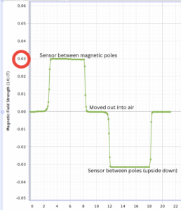
- Magnet Strength: 0.03T, 300Gauss – Confirmed magnet strength with PASCO field sensor:
Recreating Faraday’s Experimental Procedures
| Faraday Drawing | Faraday Observations | My Experiment | My Results |
Original Test (Fig. 7)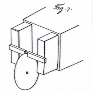 |
“88. the instant the plate moved, the galvanometer was influenced, and by revolving the plate quickly the needle could be deflected 90° or more”(Faraday Experimental Researches in Electricity Vol I, 26) | Faraday experiment confirmed ✅
On spinning the wheel, there was a clear deflection in the galvanometer needle |
|
| Exp.2 Reversing Motion
(No Diagram) |
“91. every other circumstance remaining the same, the galvanometer needle was deflected with equal power as before; but the deflection was on the opposite side, and the current of electricity evolved, therefore, the reverse of the former”(Faraday Experimental Researches in Electricity Vol I, 27) | Faraday experiment confirmed ✅
Switching the direction of motion of the disc reversed the flow of current causing the needle to deflect in the opposite direction. |
|
Exp.3 Distance from Magnet – Fig.9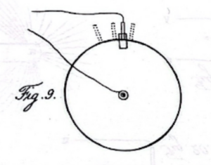 |
“92.When the conductor was placed on the edge of the disc a little to the right or left, as in the dotted positions fig.9, the current of electricity was still evolved … This occurred to a considerable distance, i.e. 50° or 60° on each side of the place of the magnetic poles”(Faraday Experimental Researches in Electricity Vol I, 27) | Faraday experiment confirmed ✅
On moving the contact on the disc further and further from the magnet, the amperage decreased proportionally. |
|
Exp. 4 Off Center (Fig. 10)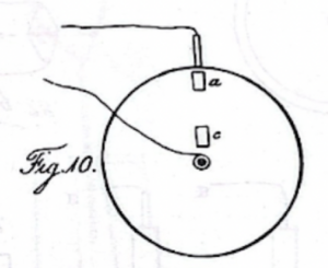
|
““93. On raising the plate, so that the magnetic poles were entirely hidden from each other by its intervention, (a. Fig. 10,) the same effects were produced”(Faraday Experimental Researches in Electricity Vol I, 27) | 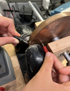 |
Faraday experiment confirmed ✅
Current is still detected when contact is moved closer to the center of the disc. However, as the pick-up moved in closer, I was recording weaker currents. |
Exp 5. Contacts on Either Side of the Magnet (Fig. 11, Fig.12) 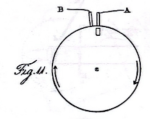 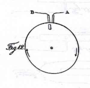 |
“95. if applied as in fig.11, a current of electricity through the galvanometer was produced; but if their place was a little shifted, as in fig.12, a current in the contrary direction resulted”(Faraday Experimental Researches in Electricity Vol I, 28) | Faraday experiment confirmed ✅
When the black wire was held above the magnet, the galvanometer needle deflected to the right (Fig.12), and when the position was moved down, the needle deflected the other way. |
|
Exp6. Equidistant From Magnet (Fig. 13)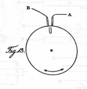 |
“96. when the two conductors were equidistant from the magnetic poles, as in fig.13, no current at the galvanometer was perceived, whichever way the disc was rotated”(Faraday Experimental Researches in Electricity Vol I, 28) | Faraday experiment confirmed ✅
Spacing the pickups equally on either side of the magnet results in 0 current – the current coming from either side cancels out. |
Confirming Experimentation w/ COMSOL Modeling:
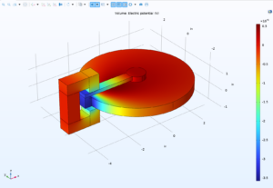
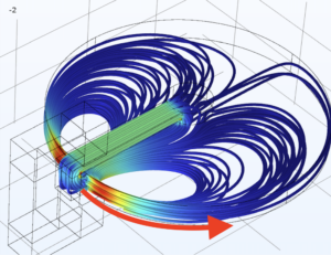
I modeled Faraday’s unipolar generator using the exact specifications of my physical model in order to get accurate simulation results. Unlike COMSOL’s stock Unipolar Generator (with a uniform magnetic field), my model uses U-magnet with a non-uniform magnetic field concentrated over one part of the disc (0.03Ts):
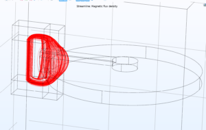
Current Density Streamlines(A/m^2) Electrical Potential (V)
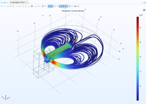
Exp1: As we can see in the current density model, the eddy currents formed in the disc cause a current to surge through the green contact from the edge of the disc to the middle; its clear that we should expect a current.
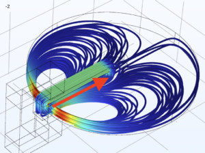
Exp2: Reversing the direction of the disc changes the direction of the current flow. When I changed velocity from positive to negative, the current in the model switched direction (as demonstrated by the arrows on the streamlines).
+18 m/s -18m/s
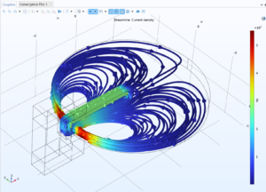
Exp3: Looking back at the current density model, we can see that as we move further and further from the magnet along the perimeter, the current density decreases, confirming experimental results.
Exp4: As we move towards the center of the disc from the edge, the strength of the current again decreases. While it doesn’t seem that faraday took note of this phenomena in his scientific journal, this is reflective of my experimental results.
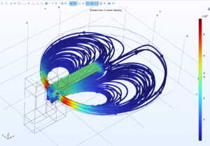
Exp5: Holding a pick-up above the magnet would follow the direction of current of the eddy current on that side of the magnet, while holding it below would follow the direction of current of the eddy current below the magnet. My comsol model shows that the eddy currents above and below the magnet move in opposite directions, so we would expect reverse deflections of the needle. This again confirms experimental results.
Exp6: Since my comsol unipolar generator shows that the current above and below the magnet flows in opposite directions, so if two pick-ups were equally spaced above and below, the current entering each would cancel out, not build up. Once again, experimental results are confirmed by comsol.
Conclusion:
Recreating Faraday’s unipolar generator using his old journals and lab notebooks was a success! My experimental results were nearly identical with both Faraday’s findings, and my COMSOL simulation. For additional explanation on how the currents in the generator are produced, take a look at my page on eddy currents.
Compressed COMSOL 6.2 file – Tesla’s Unipolar Generator (To Scale)