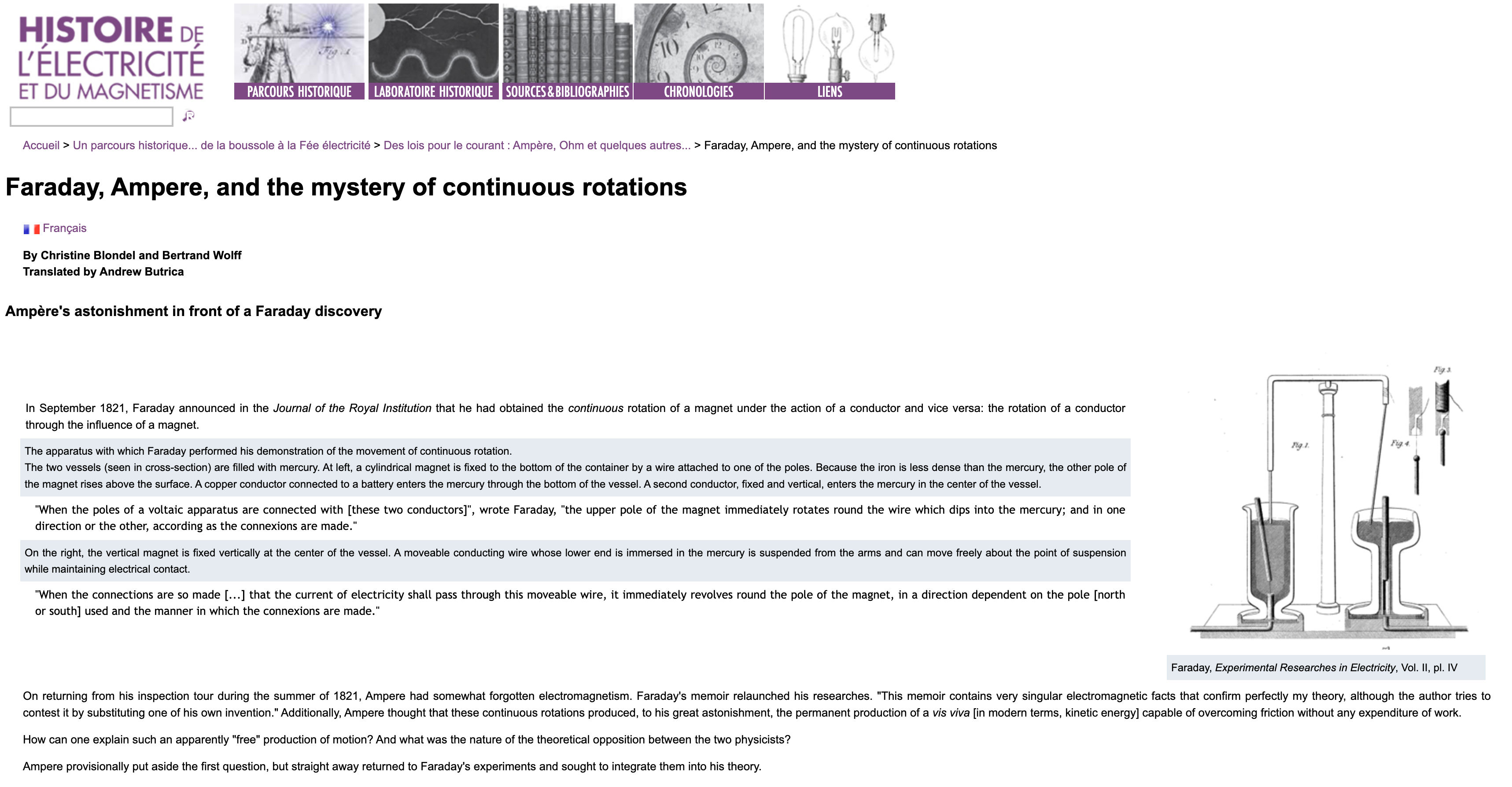
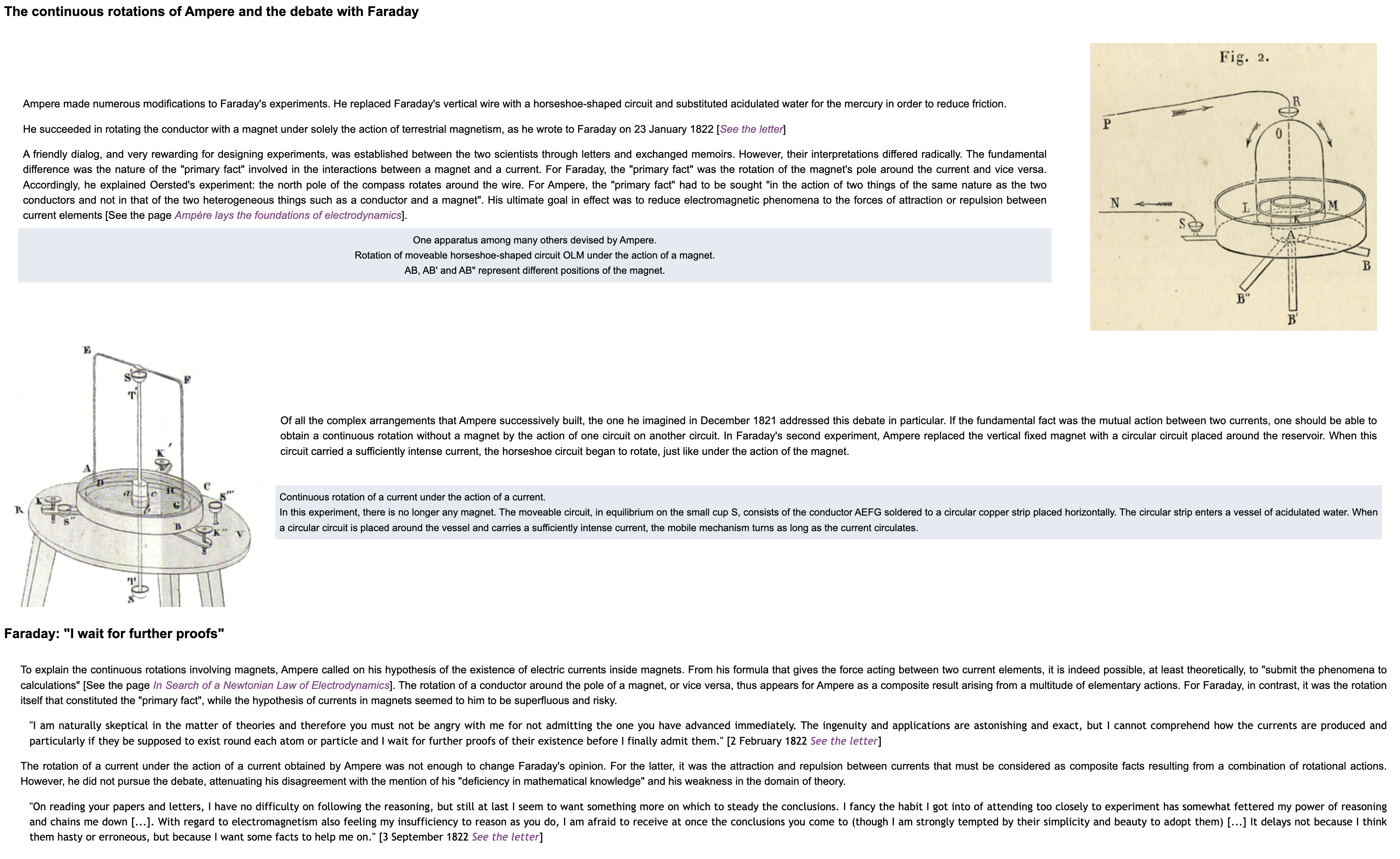
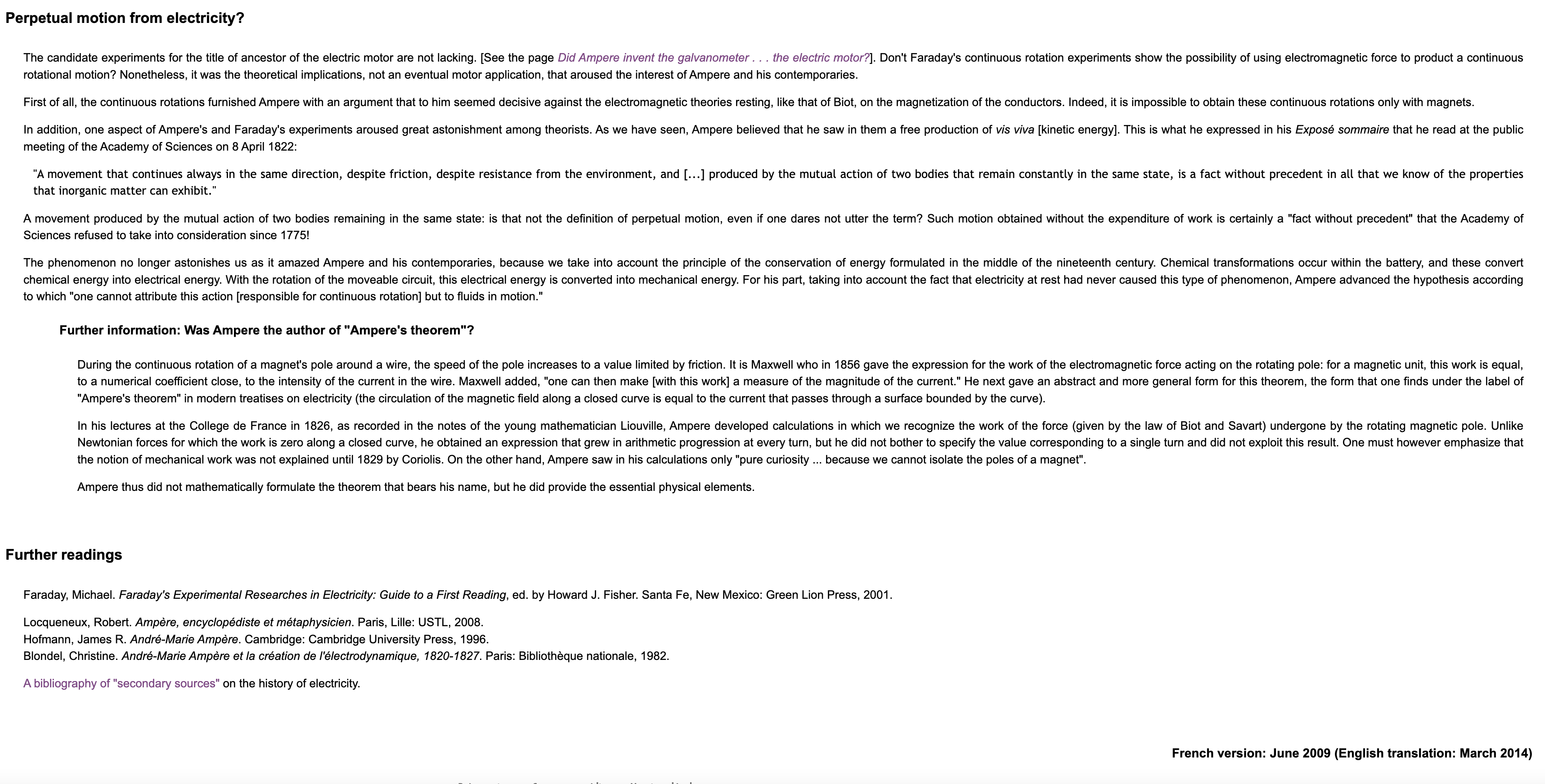
Philosophical Magazine 1822 – Ampere’s Rotator improved by Marsh
Ampere Rotator
This project studies a rotating conductor device conceived by André-Marie Ampère and studied by Joseph Henry during his time as a professor at Princeton in the 1830s. In his lectures, he demonstrated how a current-carrying wire could rotate around a magnet, using what he called a “rotating conductor” to demonstrate the connection between electricity and motion. Professor Henry shared the setup with other scientists through diagrams in his letters, and from this it is clear that the rotating conductor was an early precursor to the electric motor.
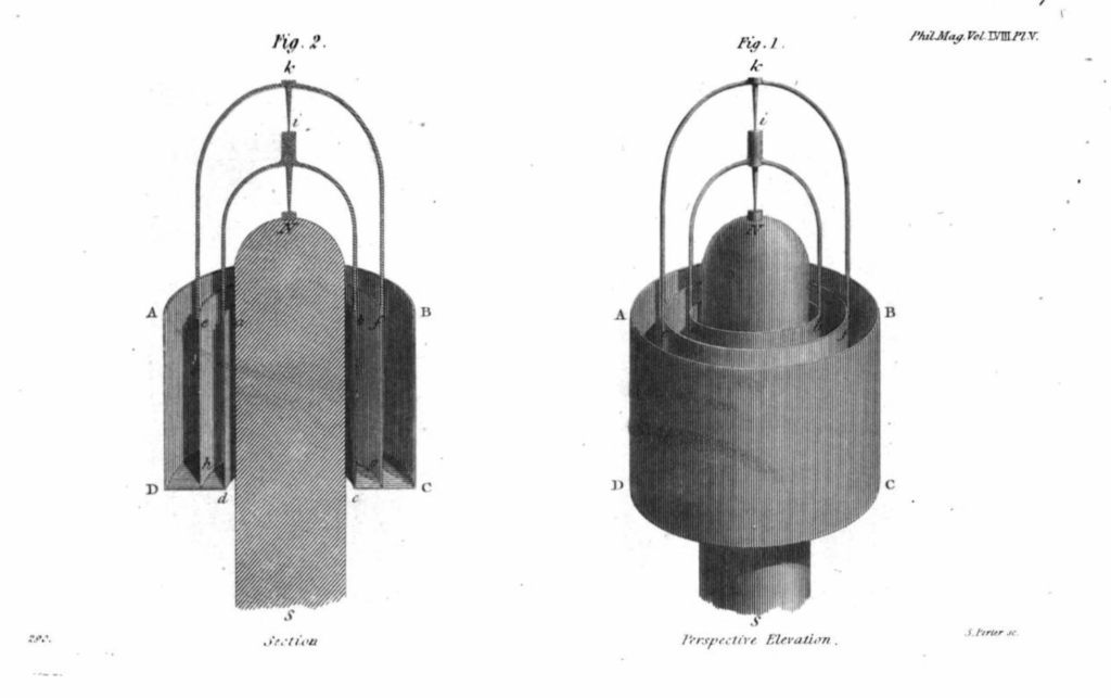
The ampere rotator, which Ampère discussed in 1821, consists of two hollow cylinders of differing size coated in copper, which are then placed and soldered inside one another. There is a hole drilled in the center of this apparatus. The inner cylinder has a wire arch soldered to its diameter. Atop this arch is a pin, on which a secondary larger arch is balanced. The larger arch has zinc plates soldered to the end of each leg, of which do not make contact with the surface of either copper cylinder but rather hang inside the cavity. The space between the two cylinders is to be filled with an acid, which completes the circuit. Then, a magnet can be inserted into the central hole of the device, causing rotation of the larger balancing arch.
Below you can view a letter from Joseph Henry to Benjamin Silliman on March 22nd, 1836 containing a digram and description of the device.[/vc_column_text][/vc_column][/vc_row]

How did Joseph Henry used the rotator? There are detailed descriptions of the device including measurements and materials in his notes. In addition to this textual analysis, the original rotator studied by Joseph Henry could be used. The measurements of the physical device confirmed that the measurements and materials were the same. The next step was to model the rotating conductor in Fusion. The device is made primarily of copper with zinc squares attached at the end of the copper horseshoe. Modeling this in Fusion 360 reproduced the original device mimicking its rotational capabilities:

After creating a 3d model of the device, the next step was to replicate Henry’s experiment. To create our replica, we found a copper cup and pitcher set which could be further modified into the base of the rotator. Using a lathe alongside Professor Littman, we cut two cylinders out of the cup and pitcher. These cylinders were then soldered one in the other to make the base. We sanded both the pitcher and cup in order to have a pure copper cylinder.


From here we then began to create the two arches. These were made from 1/16” diameter copper wire that we straightened before bending. Through trial and error, we were able to create both the arches for our replica using D.I. wire’s wire bending device. The smaller of the arches was then soldered in place. A small hole was drilled into the top middle of the arch, and a small piece of iron wire was inserted, creating a pivot. An equal sized hole was then drilled half way into the bottom middle of the larger arch, so that it could be placed securely onto the pivot and freely rotate. Once this was complete, we soldered zinc plates to each end of the larger wire arch.

After this, our design was ready to be tested. We diluted Sulfuric acid with water and poured it into the basin of the rotator. Then we used a small magnet and interacted with the rotator. From this, we noticed inconsistent and weak rotation, indicating that something was not working within our design. To figure out the issue, we first attempted increasing the acid concentration. This has little to no effect. Our second guess was that there was an issue with electrical contact between the big and small arch. Using an ammeter, we measured the electrical current between multiple parts of the device. Through this, we determined that electrical contact was the most likely issue with the device. As a result, we added in bigger zinc plates to increase contact and current and retested. This allowed the device to spin more consistently and with greater strength.
The original rotator was used by Joseph Henry in his teaching (1832-1846) to showcase electromagnetism and its uses for motion. Devices such as the Ampere rotator showcase applications of chemical and electrical energy in a simplified way, making significant waves in electromagnetic understanding that allowed Joseph Henry to create one of the first electric motors.
A detailed description of this motor can be viewed here
Through Joseph Henry’s experiments and discoveries, he helped to lay the groundwork for the future invention of the modern DC motor, providing power to millions of devices today.
Additional Information:
This excerpt is from The Papers of Joseph Henry, which document Henry’s pioneering work in electromagnetism and experimental apparatuses.
Exp. 4th. *To shew the revolution of a large Ampere’s cylinder by means of the coil.*⁹
Fig 4th.
The coil remains in its horizontal position and a large Ampere’s cylinder or bucket b is placed in the centre. When the bucket is charged with a strong solution of acid (Nitric) and the current transmitted through the coil, the moveable part of the apparatus begins to revolve with considerable velocity; when the direction of the current is reversed, the motion stops and then recommences in an opposite direction. The motion will be a little more rapid, if the bucket be supported as shewn in the figure, on the end of the iron cylynder described in the last exp, this becoming magnetic reacts on the revolving apparatus and increases the effect. The experiment however is more pleasant without the use of the iron, although the motion is less rapid.
This is a highly interesting experiment when the motion is properly produced. The bucket I have used is nearly 6 inches in external diameter. The space between (a & b Fig 7)* the internal and external cylynder for the reception of the acid and the moveable zinc cylynder is about ¾ of an inch wide and about an inch deep. The two metalic arches e, f are made of thin sheet copper nearly ¼ of an inch wide and painted white so that their motion may be distinctly seen at a distance. The whole height of the apparatus is between 8 and 9 inches. Every part should be made as light as possible, the bucket of very thin copper and the zinc cylinder of thin zinc plate which can be easily renewed. The one employed by me is so light that it makes several revolutions when strong acid is first poured in by the action of the magnetism of the earth, alone.
Exp. 5th. To exhibit the revolutions of mercury with the coil¹⁰
Fig. 5th.
Place a plate of mercury in the centre of the coil on the top of the iron cylyender mentioned in Exp. 3d. Also, place an end of the coil in the mercury at the side of the plate at e; the other end of the coil being in connection with one pole of the battery and the current completed by means of the wire d, which also dips into the plate of mercury on the oposite side at f. When the battery is put in action the mercury begins to revolve in a whirlpool around the point of its surface which is immediately above the end of the iron cylyender on which the plate rests. When the current is reversed, the motion of the mercury is changed. The revolutions may be shown at a distance by throwing on the surface of the metal some pieces of light substance which will partake of its motion and render it more perceptible.
Exp. 6th. To exhibit powerful magnetic induction with the coil.
Fig. 6th.
Represents the coil placed vertically with a large piece of iron a (the lifter of my large magnet weighs 27 lbs.) in the centre. b, c represents a piece of bar iron about 3½ feet long bent into the form of a horse shoe and placed over the sides of the coil so as to support the weight in the centre by the magnetism developed when a current is transmitted through the coil. The face of the horse shoe and the iron should be ground to each other. The great power may be shown by suspending weights to the lifter from below.
NB The results will be more energetic with a large battery than a small one. I have ex[ecuted] these experiments with a battery of a single element exposing about 50 feet of zinc surface to the action of the acid.
Modeling Marsh’s Device in COMSOL
*Remanent flux density Br=.6
Magnetic field lines: 

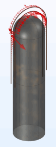
Marsh’s Device was a significant improvement on Ampere’s because it proved that the arms could rotate in opposite directions when the circuit path led to opposite directions of electron flow. Also, notice the shape of the magnet. The head is curved, and modeling in COMSOL showed that the magnetic field lines (which influences lorentz force and thus rotation) act perpendicularly to the arms of the device, maximizing its effect. Marsh claims it can rotate at “120 in a minute”, faster than any number Ampere listed.