3. Groups:
Bottom End
Grace Brightbill and Conor Melbourne


Clutch – Trans
Alex K. and David
A clutch is a key component in any internal combustion engine that supports gear-shifting. The clutch acts as a buffer between the power created by the engine and the power transmitted to the transmission, and the rear wheel. It does this by using frictioned plates that are compressed together, which can be pushed apart. When the plates – called clutch plates – are pushed together (usually by a spring inside the clutch), the power from the engine is transmitted to the transmission; when it’s pushed apart (by “releasing the clutch”) the engine can keep spinning without powering the transmission. This is important because when you’re shifting gears, you don’t want your powered shaft (read below!) to keep turning at a high velocity, or else a gear’s tooth might chip or crack when it is shifted into place.
In the third figure above, you can easily see the sets of black-colored clutch plates (item #26), with teeth that extend into the clutch basket (item #14), interlocking with the metal plates (#25) which connect to the driven shaft.
Another thing that the clutch is used for is when you’re speeding a bike up from neutral when starting it. As we learned in class, you can’t start an engine in gear or else the whole bike will drive away. Instead, you put the bike into the neutral gear, where no power is transmitted from the engine to the rear wheel, so that the engine’s crankshaft can start turning without the bike rolling away. When putting the bike into gear from this, you can’t simply shift from neutral to first. If you did, one shaft would be rotating at several thousand RPM (the typical speed of an engine’s crankshaft) and the other would be sitting still; when you tried to connect them something would very likely break (such as the engine stalling or a gear chipping). Instead, we pull out the clutch while the engine is still in neutral, then put the bike into gear (with the clutch still held). This way, the bike is in gear but there is still no power from the engine to the clutch. We can then slowly let the clutch back in by releasing the clutch handle, which slowly accelerates the bike because the force is now transmitted by cork friction pads, which work in both static and kinetic friction, rather than metal gears.
Our Clutch
For our Clutch, we had to disassemble the clutch basket, thoroughly clean the metal interlocking clutch plates, and replace the worn-out cork plates with new ones. Before re-inserting the restored clutch, we made sure that all the inner materials were well-soaked in clutch fluid, which helps increase the static friction between clutch plates. We also had to make sure that the clutch springs were tight enough, because loose clutch springs can make the engine impossible to start: if the clutch plates simply slip past each other when the driver kicks the kickstarter, then the crankshaft won’t turn.
Why cork?
One last question we had was why our clutch plates used cork. In our daily lives, we almost never see cork outside of wine bottles, yet here it was in this random engine part. Upon closer inspection, cork turns out to be an excellent material for this purpose because it has a high coefficient of friction, which determines how much force it can transmit when pushed or slid against something. Formerly, asbestos was used in clutch plates because they had this same property (and were in fact even better at it!) but thankfully the harmful effects of asbestos lead to its replacement. Our clutch basket is intriguing in its use of cork because it existed some years after asbestos was replaced, but before the next major breakthrough in clutch plate material was developed: kevlar. In the modern day, kevlar is frequently used as a clutch plate material because it has an even higher coefficient of static friction, and it lasts longer than cork.
Why transmission?
The transmission is used to change the gearing between the engine and the driven wheel(s), to change the ratio between the number of revolutions of the engine and the number of revolutions of the driven wheel. It is very helpful for a vehicle powered by an internal combustion engine to have a range of gears. If the ratio is high (many engine revolutions for one wheel revolution), then the vehicle will have a lot of power, but its maximum speed will be low. If the ratio is low, then the maximum speed will be high, but it will not have a lot of power (for example when ascending hills), and it will have to accelerate very quickly from a standstill — its minimum speed will also be high. Thus, it is best to have a transmission that lets you change the gearing ratio to best suit the situation.
In the diagram to the left, above, the green shaft transmits the power from the engine, and transfers it through a gear to the red shaft, the layshaft (also called a “countershaft” when it spins in the opposite direction from the drive shaft). The layshaft then transfers the power to the blue shaft, the main shaft, through one of several possible gear combinations, each of which has a different ratio between the number of teeth in the gears. The driver can change which combination is engaged using the selection fork, which slides the gears in and out of position.
Our Transmission
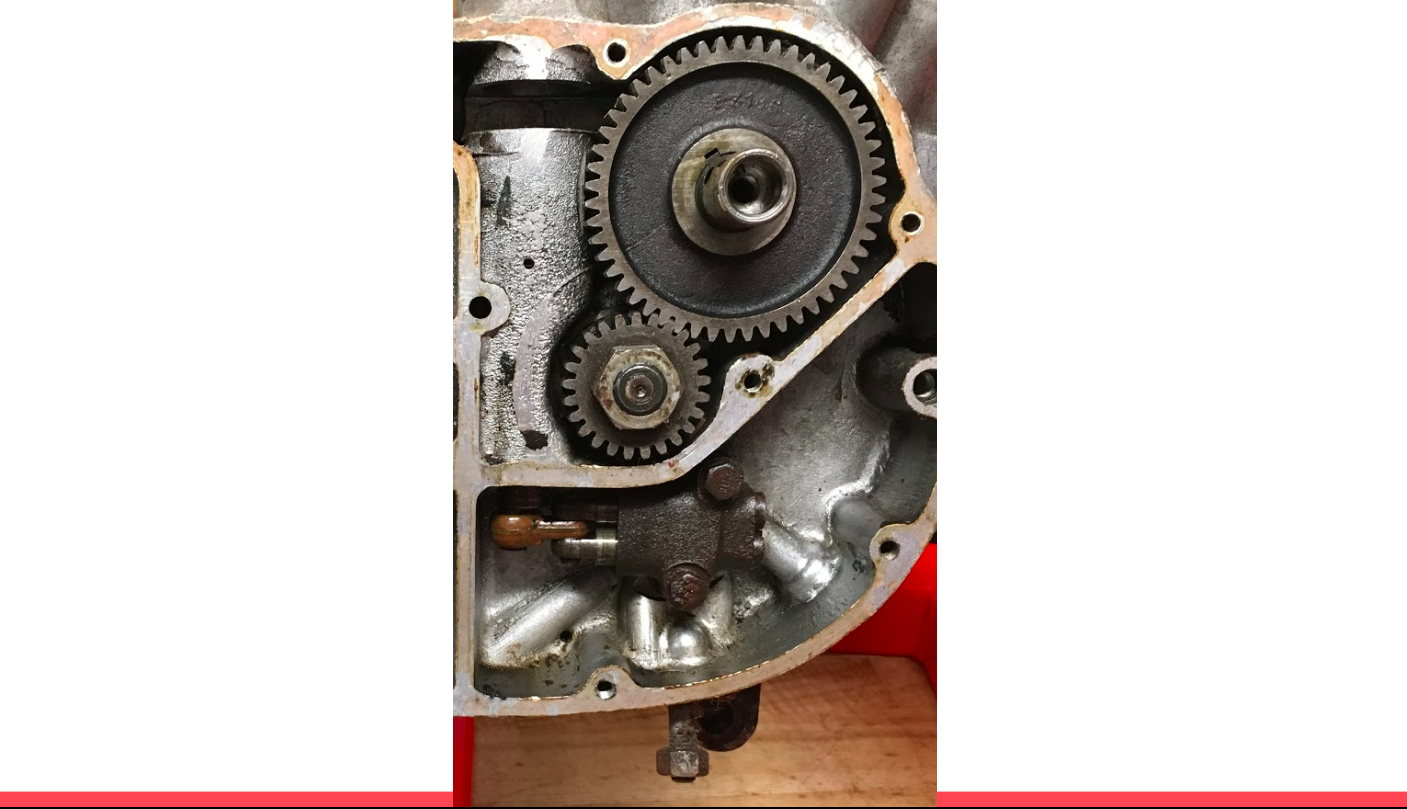
Our task was to take the transmission apart, clean it, inspect it for damage, and put it back together. When we examined it at first, it was not very clean, as you can see in these pictures:
![]()
We created this flowchart to demonstrate how the gear ratios work together. On the far left you can see the engine, and its sprocket below it. That sprocket has 19 teeth, and the sprocket in the clutch basket has 48 teeth, so the ratio is 2.53x — every 2.53 rotations of the engine sprocket produces one turn of the clutch sprocket. The clutch assembly then drives the transmission, which has variable ratios depending on which gear it’s in — from 1x to 3x, depending on the gear. Then that drives the rear sprocket, which has 17 teeth, which turns the wheel sprocket (through a chain) which has 46 teeth, with a ratio of 2.71x.
Thus, the overall ratio is 2.53 x T x 2.71, where T is the transmission ratio. Here are the charts to demonstrate gearbox ratio, which are referenced above, and the overall ratio — roughly calculated by that formula — taken from the manual, which represents the ratio between turns of the engine and turns of the rear wheel.
![]()
Calculations:
![]()
Demo Gearing
Finally, you can see here a picture of the gearings in our transmission. You can see the forks in different positions, which shift the gears around, engaging the different gears.
![]()
Thank you for reading!
Detailing:

Electrical
Ricky Feig
Components
•Lighting and ignition Switch
•Wire Harness
•Head Lamp and Tail lamp
•Stator
•Rectifier
•Battery
•Coil
•Contact Breaker
•Horn
•Produces electricity
•As the motorcycle runs, a magnetic wheel spins and induces electricity in coils in the stator
•As the cam spins faster, the induced current increases linearly

Points:
•The points ignite the fuel when the engine is approaching top dead center
•The capacitor is charged via the battery.
•The points timing is controlled by centripetal force.
•As the cam spins faster two weights on spring spread apart. This forces the spark to occur sooner in the cycle
Rectifier:
Horn:
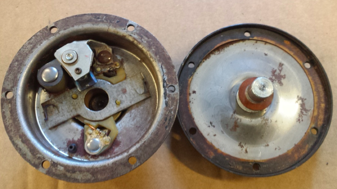
The horn was broken
•Most likely causes: the timing screw came off and pieces inside got stuck
•To repair we had to drill out the rivets and reassemble the inside
•Now it works!
•Piston is a permanent magnet
•Current runs through horn and creates magnetic field in coil
•Piston is pulled down and separates points
•Piston is pulled up by the drum acting a spring
•Points pushed back together
Link to PowerPoint of this presentation:
Fork
Brendan O’Hara
Jake Sawtelle

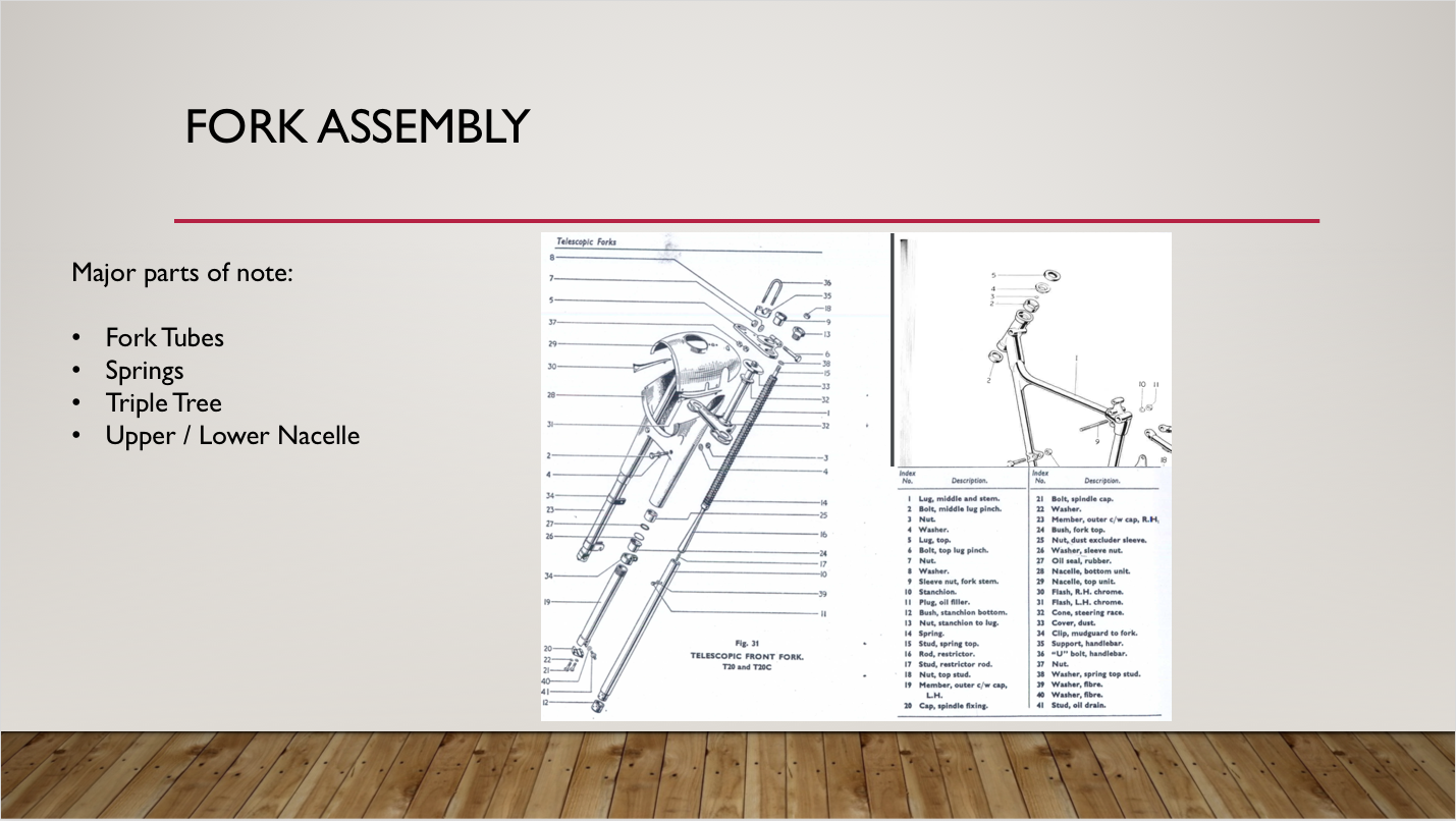
Frame – Carb
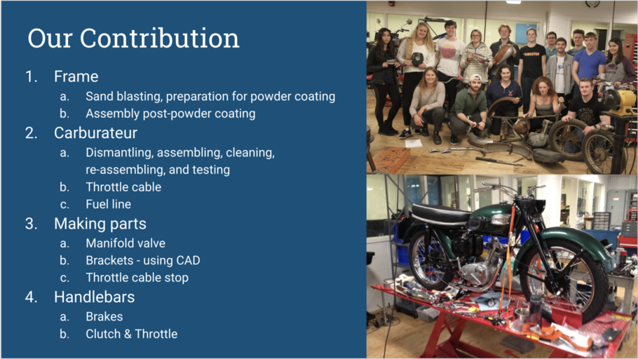
Our tasks over the semester were the following:
-
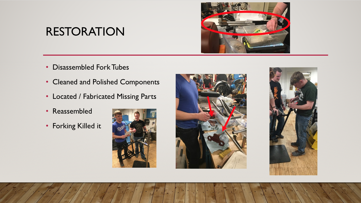
First, we worked on the frame. Our job was to assess it for weak points or cracks. We did this by using the sand blaster, which will be discussed more thoroughly later. We then sent the parts out for powder coating and chroming, and after we got them back, we worked to (re)assemble the whole frame.
-
Second, while waiting to receive the parts back from the powder coated, we worked on the carburetor. Our job was to assemble a carburetor out of the parts we had in the shop. We had to disassemble multiple Amal carburetors, clean the parts, reassemble one, and test it.
-
Third, throughout the process we also had to fashion parts of our own. For example, we needed a manifold to attach the carburetor to the engine, so working with Glenn, we were able to manufacture one. We also had to fashion a bracket for the seat from scratch using CAD. Lastly we made a piece for the throttle cable.
-
Fourth, our last project was to assemble the handle bars, including the break and clutch levers as well as the throttle.
The Frame in Depth
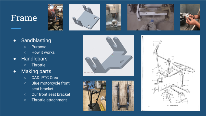
SANDBLASTING: Starting with the frame, our first job was to prepare it for powder coating. Thus, we had to assess the frame for cracks, using the sandblaster. The sand blaster uses compressed air that blows sand (or other abrasive materials) through a pointing tool to remove the top surface of material. We aimed it at each joint, and we ended up finding no issues on any of the parts.
HANDLEBARS: Then, later in the restoration process, after we had assembled the frame, we worked on the handle bars. Taking the parts we had from the chromer (the handle -bar- itself and the two levers as well as the brackets for each lever), we began to put them together. We also noticed that the threads for the levers and their brackets were unique for a Triumph motorcycle in that they were 10-32, so we went to stock room to pick up some 10-32 bolts.
MAKING PARTS: There were a few times during our restoration when we did not have all of the parts we needed, and it was either easier or more time effective to make them ourselves. The first time this happened was when we were changing the seat of the blue motorcycle. The old seat had a bracket soldered on to it, and also had attachment holes in a different configuration than the new seat, so we had to design a new bracket. In order to do this, we first used calipers to make measurements to inform our design. We then used PTC Creo to CAD the bracket we designed. We used a similar process to design a front seat bracket for our motorcycle. The other part that we had to make was the throttle attachment piece. We made measurements and created a sketch of the part. Glenn then helped us to use the lathe to manufacture this part. We then used a hack saw to cut a slit in the piece so that it could slide over the throttle wire.
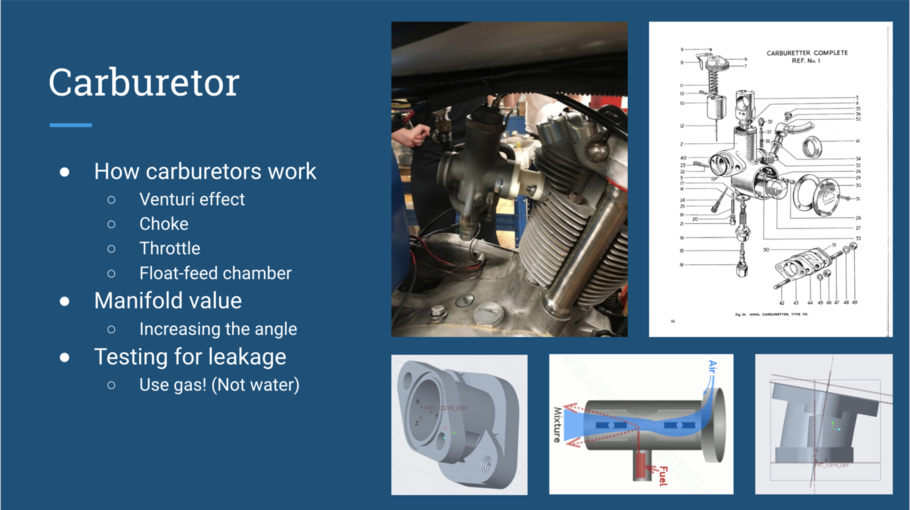
HOW CARBURETOR WORKS: Basically, the function of a carburetor is create the fuel-air mixture that will go to the engine for combustion. Central to how a carburetor works is Bernoulli’s Principle and the venturi effect. As the air flowing through the carburetor reaches the kinked part of the tube, the air speeds up and the pressure is lowered. The pressure differential that is created causes the fuel to be “sucked” up and vaporized. The carburetor choke, located above the venturi, regulates how much air can flow into the carburetor. This, in turn, can regulate the air-fuel mixture that is sent to the engine. The throttle, located below the venturi, sets how quickly the fuel-air mixture can flow to the engine. Inside a carburetor, there is a float-feed chamber, in which a small piece floats in fuel. As fuel is sent to the engine, the fuel level and float drop, and eventually, the float opens a passage through which the fuel can flow to refill the float-feed chamber.
MANIFOLD: the purpose of the manifold is to connect the carburateur to the engine. Its job is to let air and fuel into the cylinder for ignition. In the case of our motorcycle, we used a carburateur that was not meant for our bike, so we had to design a new manifold in the correct configuration. The main contribution that we made to the design of the manifold was, after seeing the white trial version shown above, telling Glenn that the angle should be increased from ten to twenty degrees. This provided for greater clearance between the top of the carburetor and the bottom of the fuel tank. It worked perfectly. Thank you Glenn.
TESTING THE CARBURATEUR: To assemble the carburetor, we first had to disassemble multiple different carburateurs to collect all of the parts we needed. Then, we cleaned these parts and assembled them into the one that we were going to use. Next, we had to test it for leaks. We originally were going to use gasoline to test but then we were told that we could just use water. We filled it with water, and our carburetor did not leak! Thus, we were done with our assembly. When we arrived at class the next day, we found that our carburetor was disgusting. Apparently, we had not drained it out enough, and the water had some sort of precipitate in it, so a strange white substance was left in the carburetor. When we tried to clean it off, we scratched off the top layer of aluminum for the carburetor, and it oxidized with the air, turning white. This led us to believe that we had not fully cleaned our carburetor, so we spent the class with carburetor cleaner attempting to clean it out completely, until we realized that we already had. Finally, we reassembled it again, tested it on the red motorcycle, and it worked! The moral of the story is that you should use the material meant to be in the part to test it. DON’T USE WATER.
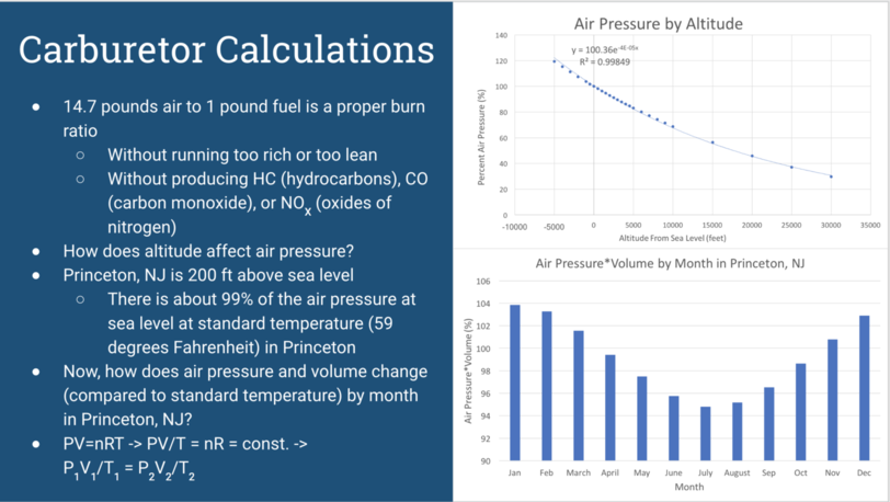
FUEL-AIR MIXTURE: As referred to in the previous slide, there is a proper fuel-air burn ratio. Based on the handout Professor Littman gave us, that proper ratio is about 14.7 pounds of air to one pound of fuel. With the proper fuel-air ratio, ideally engine would run smoothly, without excess heat, and without producing excess emissions.
ENVIRONMENTAL IMPACT: As we learned in our reading concerning carburation, hydrocarbons are raw unburned fuel, and they can pollute the environment. They are emitted in large quantities when the engine is running too rich or when there is engine misfire, which can be caused by excess heat in the engine. This excess heat could be caused by running the engine too lean. Carbon monoxide is essentially partially burned fuel and can also be a harmful pollutant if emitted in large quantities. If the engine is run too rich, there will not be enough oxygen during combustion, and carbon monoxide, rather than carbon dioxide, will be formed as a product of combustion. High cylinder temperature and pressure can lead oxygen to react with nitrogen, forming oxides of nitrogen, a third pollutant. These cylinder conditions can be a result of running the engine too lean.
CALCULATIONS: As can be clearly seen from this information, the balance of fuel-air mixture is sent to the engine is very important for both environmental reasons and for engine life. Thus, for our calculations, we decided to see how certain variables might affect air pressure, since changing air pressure would change the amount of air molecules being sent to the engine within each volume of air.
ALTITUDE: First, we explored a more straightforward question: how does altitude affect air pressure? Online we found data on the air pressure at different altitudes above and below sea level. We decided to convert those air pressures into percentages of the air pressure at sea level. This would make the data more legible to someone who did not know the scale of kPa, for example. Since Princeton, NJ is located at an altitude of about 200 feet above sea level, the air pressure is about 99% of what it is at sea level (at standard temperature, or 59 degrees Fahrenheit). This means that if you had your carburetor set properly at sea, you may want to ever so slightly lean it out in order to get a proper fuel-air ratio in Princeton.
TEMPERATURE: Next, we wanted to explore how air pressure changes by month in Princeton, NJ. To do this, we first found the average monthly temperatures in Princeton online. Then, we used the Ideal gas law, PV = nRT, to figure how out these temperatures would affect the pressure and volume of air. We solved the ideal gas law as can be seen on the slide to find that P1V1/T1 = P2V2/T2. We then solved for the pressure times volume of air in princeton, assuming that air is an ideal gas, during each month and found the percentage of princeton’s pressure times volume of pressure times volume for standard temperature. This graph shows the results of our findings. The main takeaway from this graph is that if you have your carburetor properly set in a hot month, you may need to adjust its settings during a cooler month.
Link to a PDF of this presentation:
The Top End
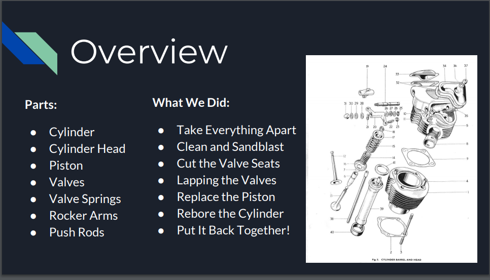
Our Parts:
1) Cylinder
2) Cylinder Head
3) Piston
4) Valves
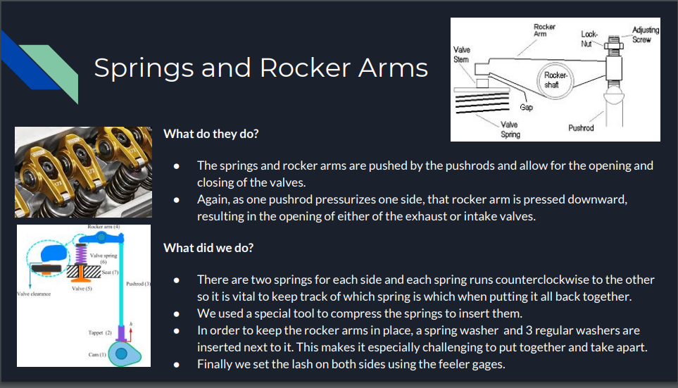
5) Valve Springs
6) Rocker Arms
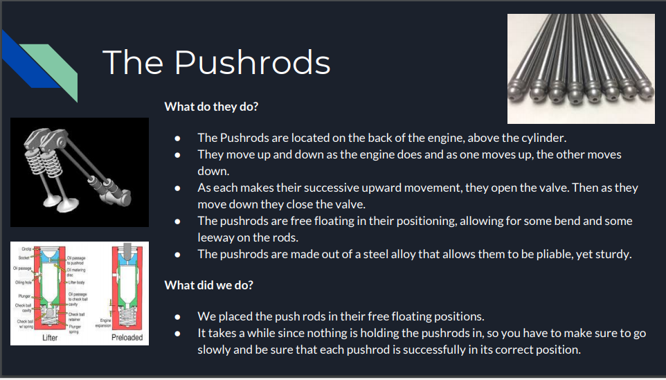
7) Push Rods
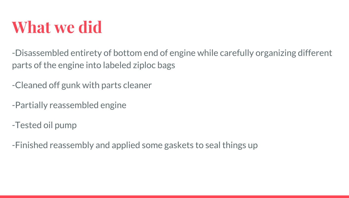
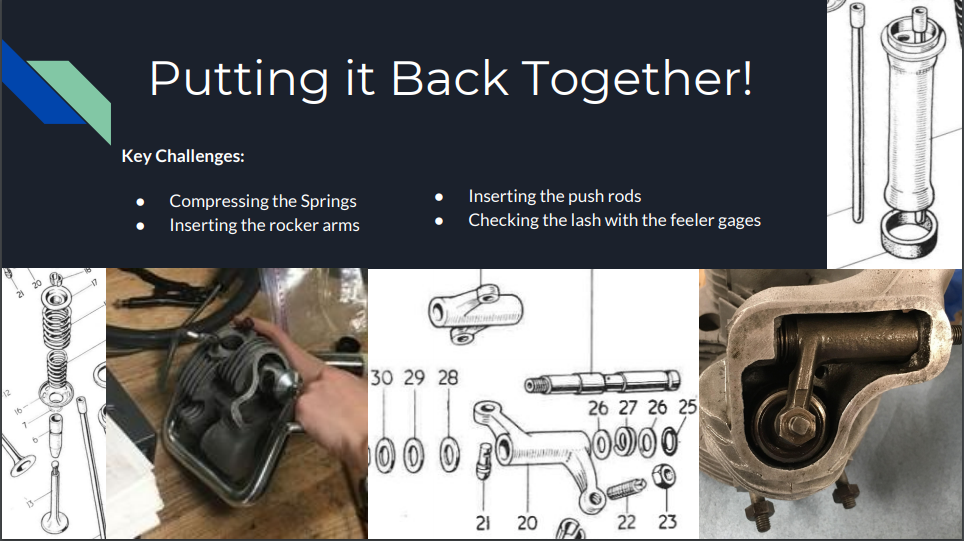
What We Did:
1) Took everything apart and inventoried parts
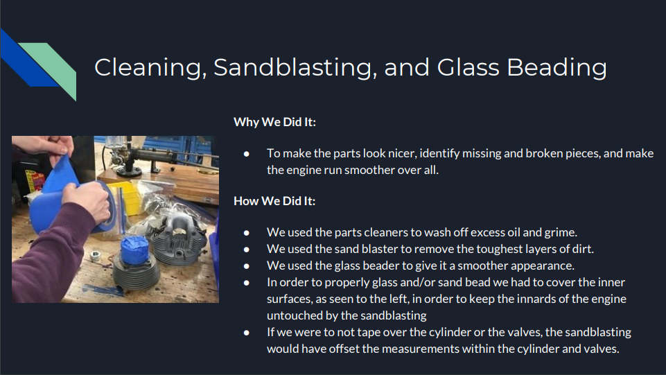
2) Scrubbed everything in the parts cleaner
3) Sandblasted the Cylinder and Cylinder head
4) Glass-beaded the Cylinder and Cylinder head
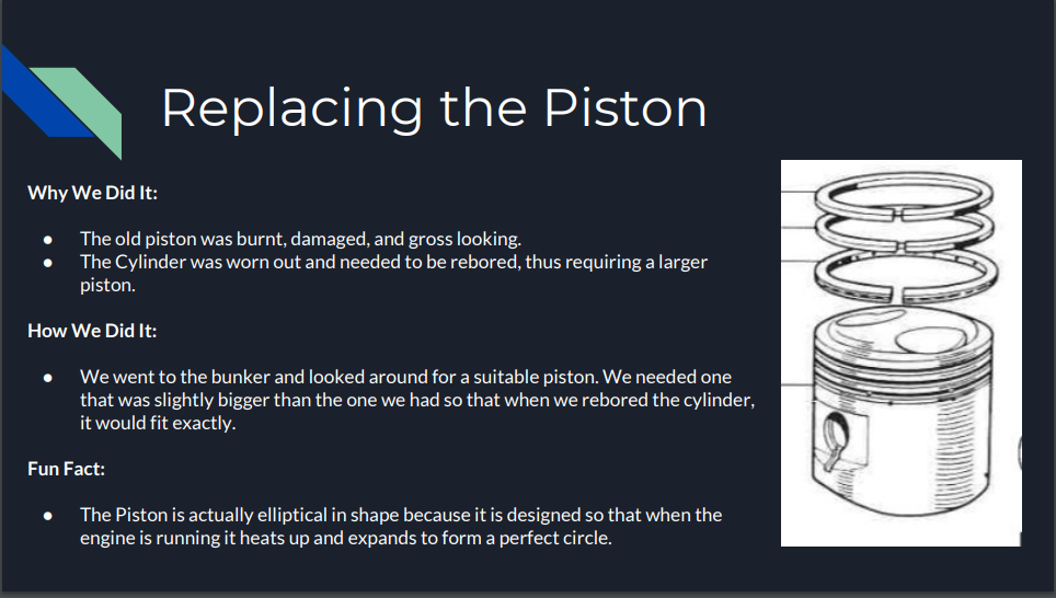
5) Ordered a new piston
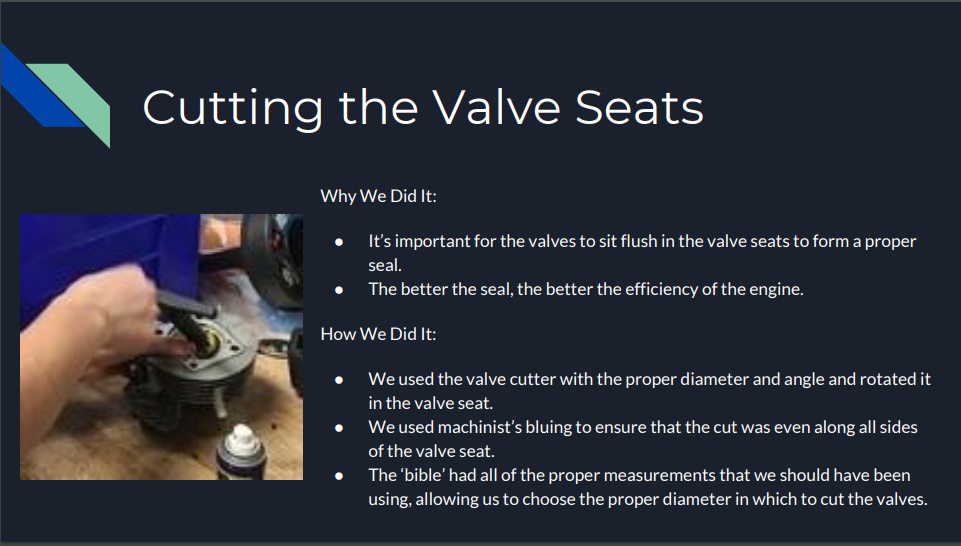
6) Cut the valve seats using the valve cutters
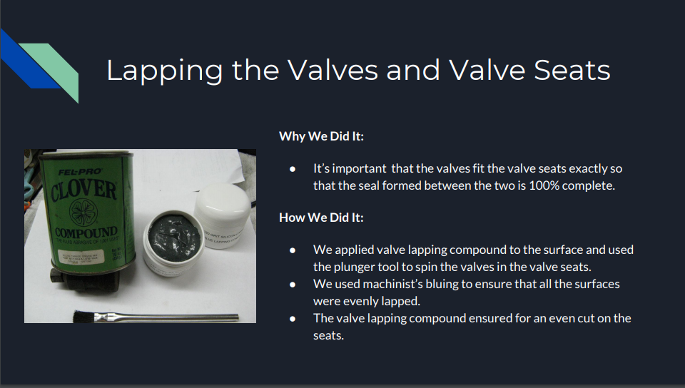
7) Lapped the valves and the valve seats
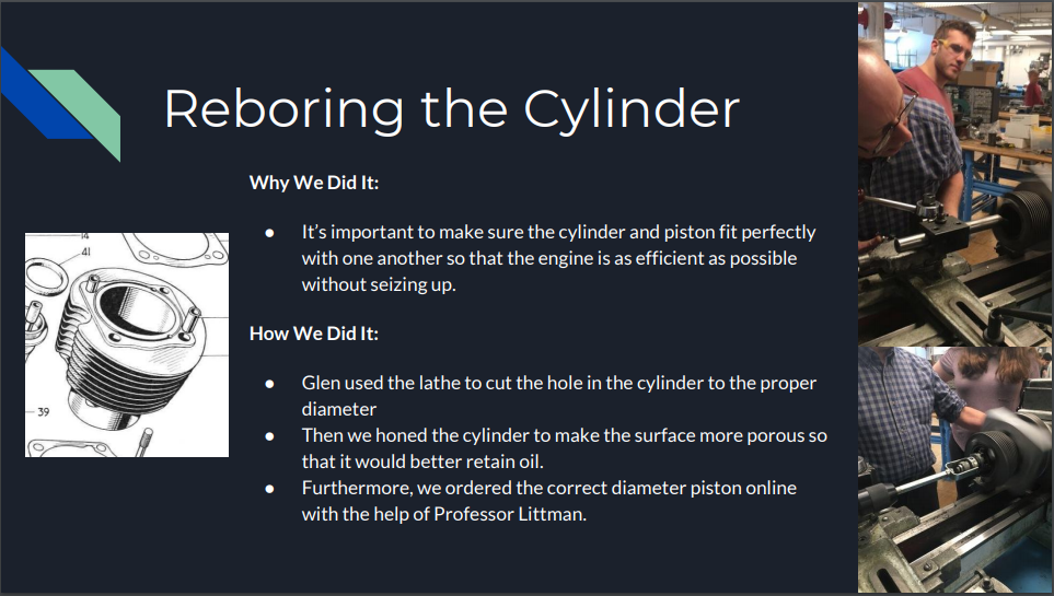
8) Bored the Cylinder using the Lathe (with Glen’s help)
9) Honed the Cylinder
10) Reassembled the Cylinder head (inserted the valves, springs, and rocker arms)
11) Attached the Cylinder to the Cylinder head
12) Attached the Top End to the Bottom End (and inserted the push rods)
13) Checked the lash with the feeler gages
14) Put the covers on the Cylinder head
15) Put the engine on the bike

Link to PDF of this presentation:
Wheels
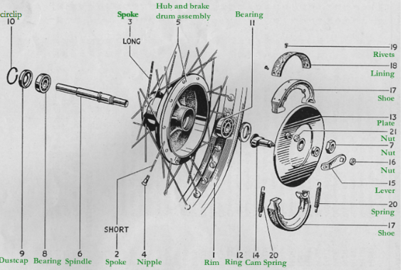
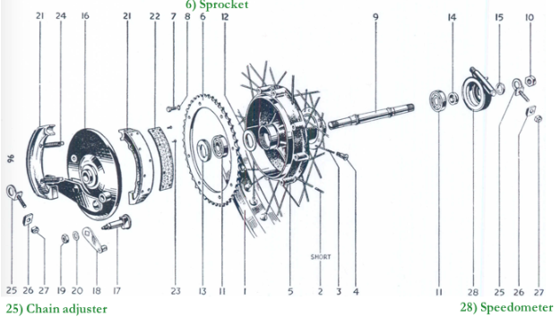
The parts of the rear wheel and front wheel are relatively similar apart from the 6) sprocket, 25) chain adjuster and 28) speedometer. The sprocket is the gear on the rear wheel that holds the end of the chain. Teeth connected with drive chain which is connected to the engine. The number of teeth on the sprocket affects acceleration, revolutions per minute (related to fuel economy), and maximum speed. (These are determined by the gear ratio of teeth between front and back sprockets.) In summary the most important parts of wheel are: The hub- within the hub are the axle and ball bearings-the spokes, and the rim.
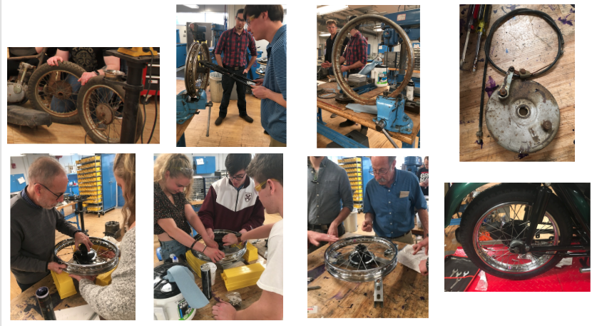
Steps to disassemble and reassemble the wheel:
-
We inherited the wheels from the original motorcycle, and we needed to take them apart. We, therefore, started with the question: What part do we need to keep in order to reassemble the wheel? After consulting with Professor Littman and Al, we determined that the two hubs and the associated hardware were the main parts that needed to be retained. We could remove the old tire, rim, and spokes, because we had ordered new parts to replace the originals.
-
On the first wheel that we approached, we attempted to place a tire removal tool between the rim and the tire, with the assistant of a lubricant. A significant amount of force was required to take the tire off. After finally removing the tire, we cut the spokes off. In light of the significant challenges encountered with the first wheel, we decided to use a saw to cut the tire off of the second wheel, and the saw penetrated the rim. Retrospectively, it would have been a good idea to keep the parts instead of throwing them out as a reference point for measurements later in the process.
-
At this point, we just had the hub, with screws in it, an axel, and the hardware that held this fixture together. We spent a few days cleaning the hubs with metal brushes and sandblasting the parts. We then sent the two hubs off to be powder coated. At various points, there were multiple hubs in the mix: some from previous motorcycles, some from the 1963-2 Tiger Cub.
-
While the hubs were being processed, we cleaned up other parts including: the screws, the axles, and other hardware.
-
When we got the hubs back, we began to put the spokes on the wheel. This was one of the more challenging parts of the assembly process. There are different spokes for the bottom part of the hub (this circle has a larger radius, meaning that the spokes are closer to the rims) and the top part of the hub (this circle has a smaller radius meaning that the spokes are further from the rim). For the top part of the hub, there are inner and outer spokes of different lengths, because some enter in the gaps on the hubs from different orientations. The spokes do not go out radially in a line from the center of the wheel to the rim; rather, they sit in a vector at an angle from the vector in order to distribute force and allow for compression to take place. It took a number of tries to properly spoke the wheels.
-
Bill Becker helped us with lacing the wheel, providing insightful advice on how to get the correct tension on the spokes and offset from the rim to the hub.
-
After the spokes were properly attached to the rim, we needed to adjust for the tension and displacement. In order to accomplish this feat, we trued the wheel. We learned the art of “truing” the wheel in which we learned how to loosen and tighten the spokes to reduce the “offset”(wobbling). This entails putting the wheel on a special stand that allows us to center the wheel. There are two categories of displacement about which we were concerned: vertical and horizontal displacement. We used a special spoke wrench to make proper adjustments.
-
To mitigate horizontal displacement, we adjusted the left and right spokes. If the wheel was offset to the left, we tightened the right side and loosened the left side to pull the wheel to the right. On the other hand, if the wheel was offset to the right, we tightened the left side and loosened the right side to pull the wheel to the left.
-
To mitigate vertical displacement, which was manifested in the form of a slight dip of the wheel as it spun, we adjusted spokes on different vertical slides of the wheel with equal turns.
-
LISTENED TO FREQ OF SPOKES
-
PERMISSIBLE ERROR 1/16 INCH
-
-
We spent many lessons trying to reduce the effects of wobbling which was a tedious challenge. Once we finally got the offset of the horizontal and vertical displacement correct, we repeated the whole process on the rear wheel.
-
After truing the wheel, we affixed the axel.
-
Lastly, using a special stand, we attached the tires to the rims.
Library
Martinelli
Photos