Basic Electricity and Magnetism Preface
Shocking, we know…
Before we can get to the exciting substance of our Tiger Cub’s electrical system, it is necessary to explain a few fundamental concepts of electricity and magnetism.
- Charge: a physical property of matter, described as either a positive or negative value, that explains the behavior of said matter, expressed in units of coulombs (C).
All matter in the universe is composed of small constituent particles, all of which have some sort of charge. In electricity, the most important particle is the electron. It is the flow of electrons that constitutes an electrical current.
- Voltage: the electromotive force or potential difference across two points, expressed in units of volts (V).
When an electrical system experiences a voltage (often introduced by an electrical “source”, such as a battery), electrical current will begin to flow..
- Current: the rate of electrical charge flow at a given point in a circuit, expressed in units of amperes (A).
The current of an electrical system describes its ability to do work. Higher amounts of current are used in situations where electrical components are required to do more strenuous tasks.
- Magnetic Field: a region of space near a magnet, electric current, or moving charged particle in which a magnetic force acts on any other magnet, electric current, or moving charged particle. (Random House Dictionary)
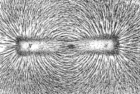
(P.C. Wikipedia)
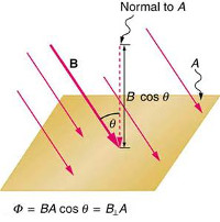
- Magnetic Flux: the amount of magnetic field “lines” that cross through a region. Areas that experience a more powerful magnetic field are said to have a higher “magnetic flux density” a.k.a. Magnetic Induction.
A changing magnetic flux can be harnessed by a coil of wire to produce an electric current. In this case, the magnetic flux can be expressed as ɸ = NBAcos(θ) where N is the number of coils of wire in the coil, B is the strength of the magnetic field, A is the area of the coil, and θ (theta) is the angle that the magnetic field makes with the coil.
In the same way a flowing electric current can create a magnetic field, a moving and changing magnetic field (or more specifically changing magnetic flux) can induce an electric current. It is by this process that generators are able to produce electricity, and the 65′ Tiger Cub is able to run.
- Faraday’s Law: a changing magnetic flux can motivate an electromotive force (emf) which in turn causes current to flow.
The final piece of electricity and magnetism we will touch on is the concept of the transformer.
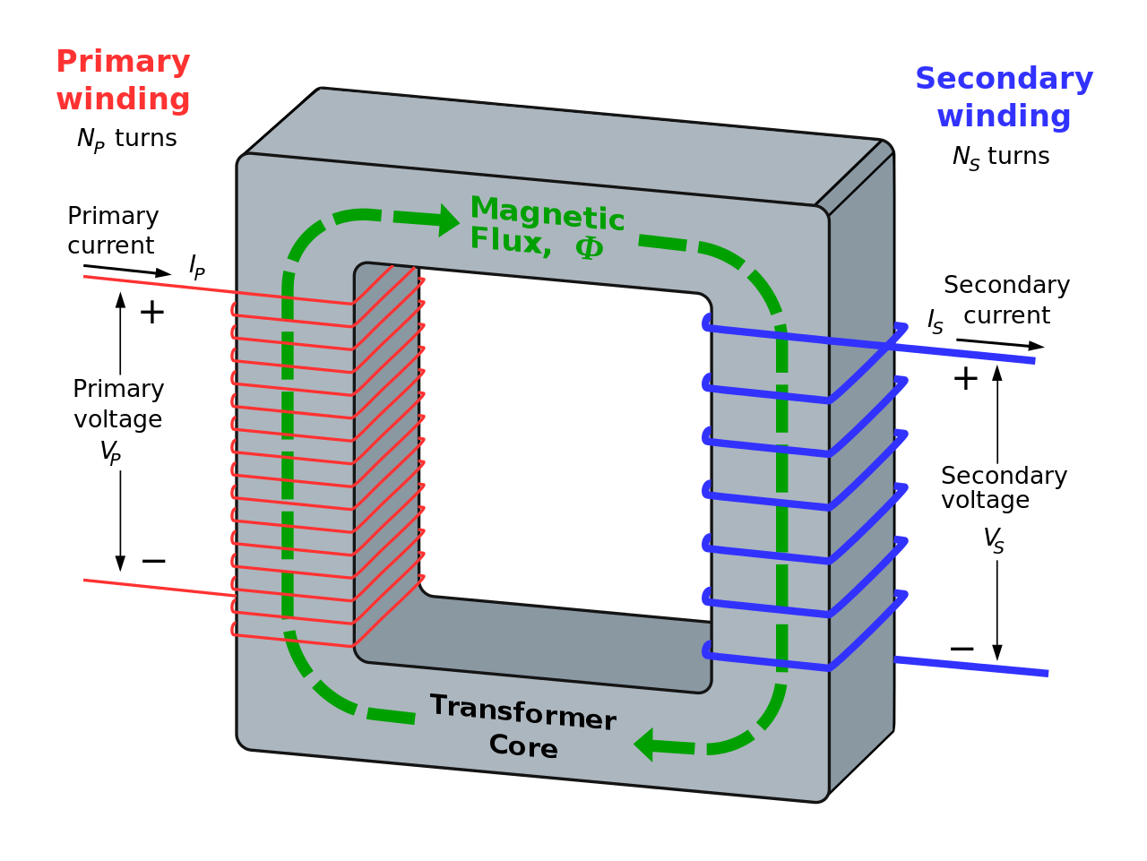
- Transformer: a device that utilizes the ferromagnetic properties of an iron (or other metal) core to raise or lower voltages.
The ignition coil on a bike, is a transformer which takes the relatively low voltage of the alternator and “steps it up” for the spark plug.There is a “primary” input side and a “secondary” output side by convention, though it can be used in either direction.The voltage and current across a transformer are inversely proportional, so a higher voltage will be accompanied by a very low current and vice-versa.
Now that we have a basic understanding of how electricity and magnetism work, let’s take a look at the specific parts of the bike that make up this system.
Alternator
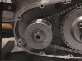
The ’65 tiger cub is an energy transfer bike, so rather than having a battery to help power the electrical components of the bike it makes all its own power. At the core of the energy transfer process is the alternator, a two-part electricity generator that consists of a large magnet called the rotor and a series of wire coils on spokes called the stater. Without this vital component, the electrical system would not function and the ’65 would not run.
 The Rotor
At the center of the alternator assembly is the rotor, a large, cylindrical magnet (really three magnets in one) that sits attached to the end of the engine crankshaft. As the engine runs and the crankshaft spins, this large part turns in the alternator and provides the changing magnetic field (see Faraday’s Law) required to generate electric current in the bike.
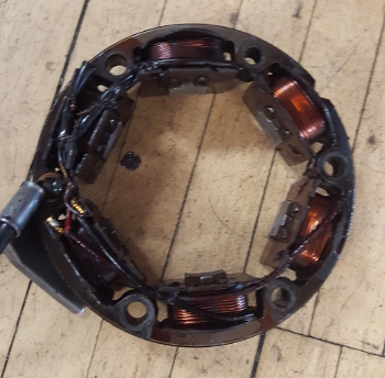 The Stater
Surrounding the rotor on all sides is a series of electromagnetic coils that make up the stater. As the rotor spins around inside of the stater, it exposes each wire coil to a constantly changing magnetic field. Through the process of magnetic induction, an electric current is then created and supplied to different parts of the bike. Certain parts of the electrical system require more electricity, and will be connected to either more coils or to a coil that has more loops of wire. For instance, the ignition coil requires a good deal more electricity than does the brake light. By working in tandem with the rotor, this core component supplies the entire electrical system with power.
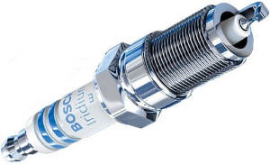 Spark Plug
This component, mounted in the top of the engine, is responsible for igniting the vaporized fuel in the piston chamber during the power stroke of the engine cycle (see the top end section for more details). The “spark gap” part of the spark plug is the little c-shaped portion at the stubby end of the device, and that’s where most of the spark plug’s work is done. After electric current from the stater is stepped up by the ignition coil, electricity is able to flow across the small gap in the spark plug for a very short period of time. It is this small spark that raises the temperature of the gas high enough to explode, which perpetuates the engine motion and turns the wheels of the bike.
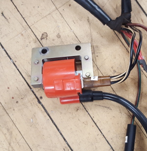 Ignition Coil
Electricity as it comes into the electrical system is at a relatively low voltage, anywhere from 4 to 8 volts. This sort of voltage is not nearly enough to pass through open air, as required by the spark plug to ignite gasoline. That’s where the ignition coil come in. The coil is a step-up transformer (see the physics preface for more information) and it raises the low voltage input from the stater to hundreds of times its input voltage for a brief moment. This moment of high voltage electricity is all the spark plug needs to ignite the piston’s gasoline and push the engine forward.
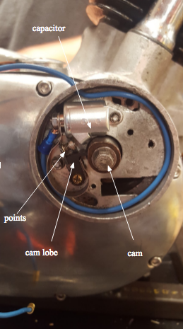
Distributor
The distributor is a device in the ignition system that routes high voltage from the ignition coil to the spark plugs at the correct time. An engine gear drives the distributor shaft, which in turn spins the cam that pushes the cam lobe, and the cam lobe opens the contact points. The distributor also contains a capacitor (or condenser), which collects charge and prevents it from arcing across the points. It is important to adjust the points from time to time, because with wear the engine requires sparks at different rates. The contact points is a switching device found in the distributor that interrupts the current flowing in the primary circuit of the ignition coil. The position of the contact points is set so that they open at the exactly correct moment needed to ignite the fuel at the top of the piston’s compression stroke.
Wiring Harness
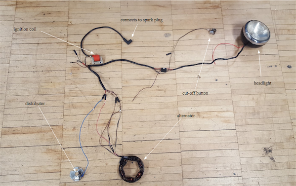
The wiring harness connects all electric components. The connections between the alternator, distributor, ignition coil, and spark plug are of course the most important. A major project of ours this semester was the restoration of the wiring harness.
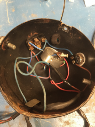 Headlamp
Other than being a headlamp, it is the hub of several electrical wires, including the speedometer lamp and high beam indicator. It took the most time to repair because of the complexity of the internal electronics. It needed a new bulb and fixture as the old assembly was falling apart.