
This method and accompanying diagram was drawn from “Electricity and the Electric Telegraph” by Goerge Prescott, on pages 140-142.
A sine galvanometer uses the earth’s magnetic field, therefore, you cannot use astatic needles which would negate this field. This means that the instrument is sensitive to external magnetic fields, so take care that the only field acting on the galvanometer is the earth’s. Remove any nearby magnets or currents that may interfere with the needle. Thus, the galvanometer needle is initially at rest within the magnetic meridian, pointing due north.
When current is passed through the galvanometer, the needle will deflect as usual. Carefully rotate the entire galvanometer on the disk to keep the needle lying within the plane of the coil until the needle no longer deflects out of this position. In this configuration, the needle no longer rotates because the torque from the coil’s field and the earth’s magnetic field have exactly balanced each other out.
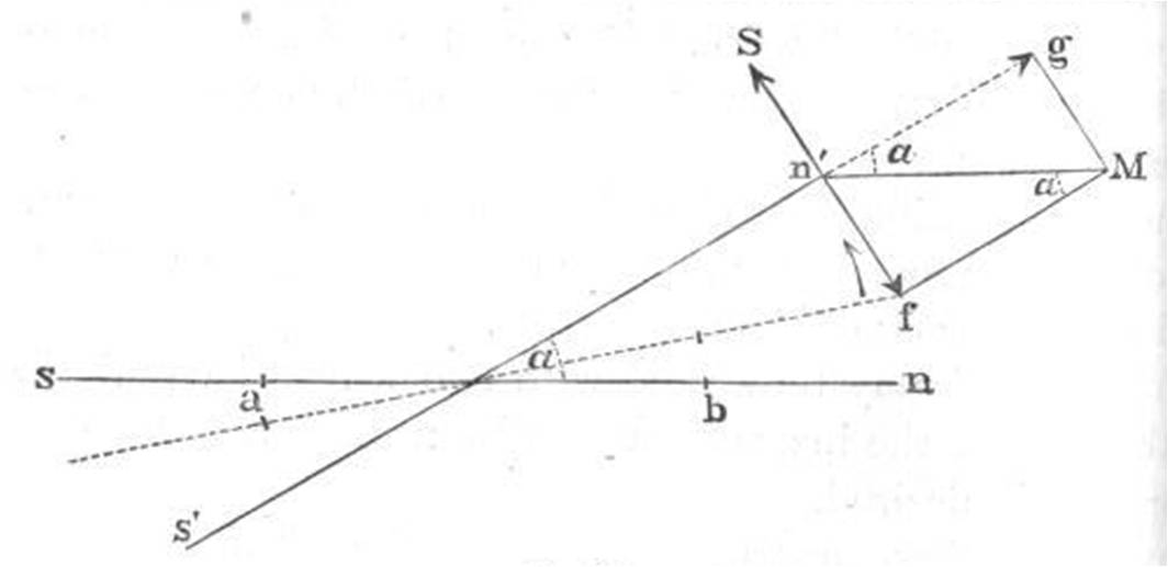
In the diagram above, sn is the needle’s original position within the magnetic meridian. The line s’n’ is the needle’s new position, after the needle has deflected and the galvanometer rotated. The symbol alpha is the angle of deflection between these two positions. The perpendicular component of the earth’s magnetic field (n’f) is equal to the the coil’s magnetic field (n’S). You can use the formula B = mu-naught * N * I / L to solve for the current through the wire, where B is the coil’s magnetic field, mu-naught is the constant 1.26e-6, N is the number of turns in the coil, I is the current, and L is the length of the wire in the galvanometer.