What are the key components in the electrical system?
- Switch
- Battery
- Alternator (Stator and Rotor)
- Coil
- Points (Contact Breaker)
- Spark Plug
The Switch
We had to wire this on/off switch into the circuit of the motorcycle. When turned on, it allows the ignition system to work.
This was very simple to do. Steps to install/work it:
1. Place the switch in the path from the battery to the coil
2. Turn the switch off: circuit is opened and the battery is disconnected from the coil
3. Turn the switch on: the circuit is closed and the battery is connected to the coil
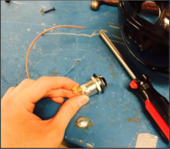
The Battery
Description:
It has 3 cells with 2 volts each, summing up to 6 volts. Each cell can be seen in the previous slide’s picture as the yellow shapes on the top of the battery.
Testing the battery:
When we measured the volts of the battery with our voltmeter, we got a higher reading (around 9 volts) than the predicted voltage.
Possible errors: this could have been because the battery was completely new or our voltmeter could have been off.
Precautions:
While installing, we had to make sure it didn’t short circuit (this would cause a fire). We also taped a rubber sheet over the top to ensure that there would not be a connection with the metal casing, which could be dangerous.
Battery vs. Energy Transfer System
Our bike is powered by a battery– but are all?
Another set-up: energy transfer
- No battery/rectifier, instead AC is supplied directly from the alternator
- Different coil needed
- Pros: compact and reliable
- Cons: requires more maintenance due to wear on points
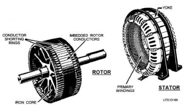
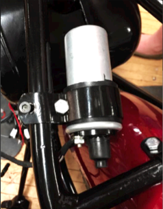
The Alternator
The alternator has two parts: 1) the stator 2) the rotor
The stator: a circle of 6 coiled copper wires that stays stationary– thus the name stator.
The rotor: a six pole magnet that’s connected to the crankshaft. As the crankshaft spins, the rotor spins as well.
How do they work?
As the rotor spins inside the stator, the rotor creates a change in the electromagnetic field around the stator. By Faraday’s law, the change in electromagnetic field creates current in the copper wires, which then results in voltage.The current that it generates is AC current, which is different from DC current in the sense that the direction of the voltage reverses.
The Rectifier
- AC: “alternating current” changes directions
- DC: “direct current” flows in one direction, + => –
- AC has a sinusoidal wave, so the rectifier’s DC output current goes in one direction
- This is basically achieved with 4 diodes.
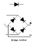
The Rectifier: AC vs. DC
The rectifier allows us to change AC into DC. But how?
It basically utilizes four diodes in order to achieve this.
Regardless of the direction of the voltage that comes from the AC, the rectifier creates a steady stream of single-directional voltage.
Diodes: one way valve, helps the one direction
AC vs. DC Visual Animation
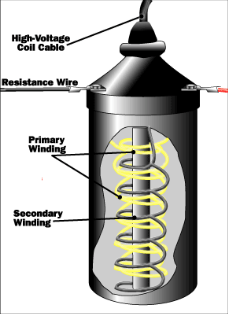
The Coil
Induction to generate high voltage needed for the spark plug: Primary Coil vs. Secondary Coil (100x more turns than primary)
Why is it so important?
It creates the high voltage that is necessary to generate a spark in the spark plugs.
How?
Induction! Within the coil there are two coils of copper:
- The primary winding
- The secondary winding
- The ratio between the two winding is what causes the voltage leverage. If it is 1 to 1,000, the 1 volt in the primary winding will become 1,000 volts in the secondary winding.
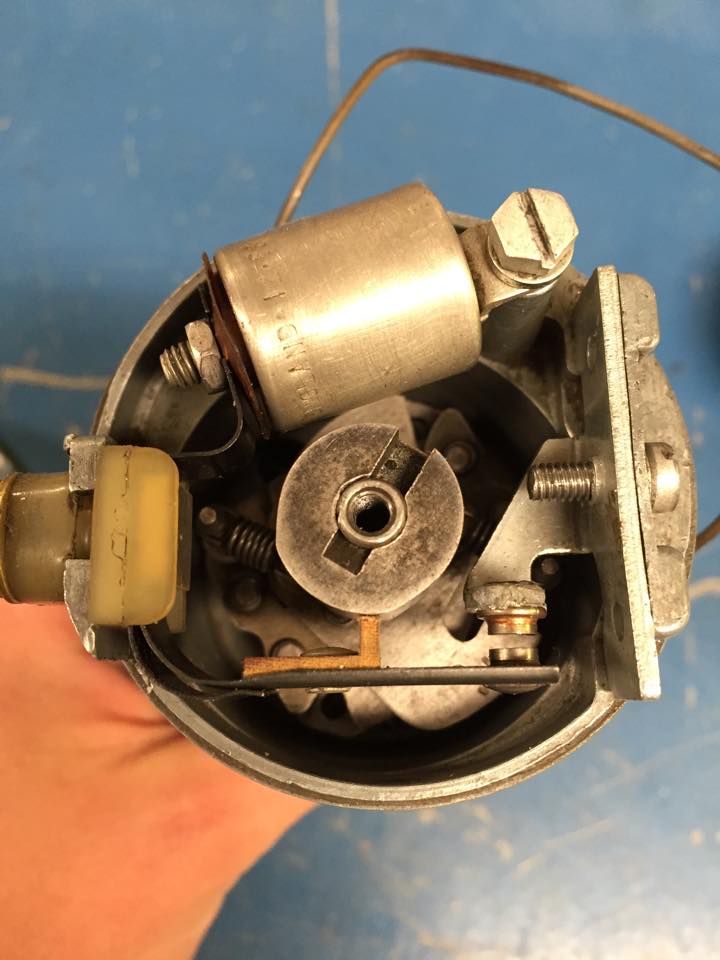
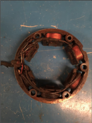
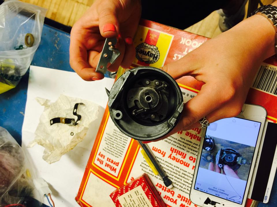
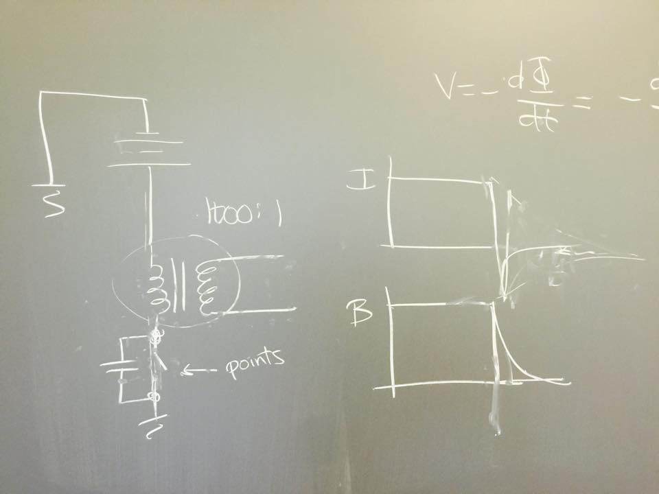
The points control the timing of the spark plug.
It achieves this with the camshaft in the middle. The oval-shaped cam, as it spins, connects and disconnects the points periodically. It is worth nothing that the cam actually rotates with respect to the RPM of the motorcycle.
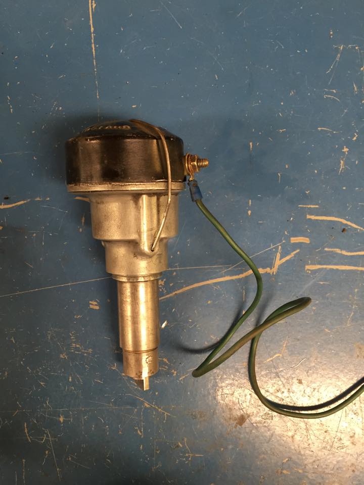
The points, located in the distributor (this is the name of the whole assembly pictured above), work with both the coil and the spark plugs; they are essential components of the ignition system. While the coil and the spark plugs concern themselves with the creation of the sparks themselves, the points work majorly with the timing of these sparks so that they occur at the optimal timing.
Assembling the Points
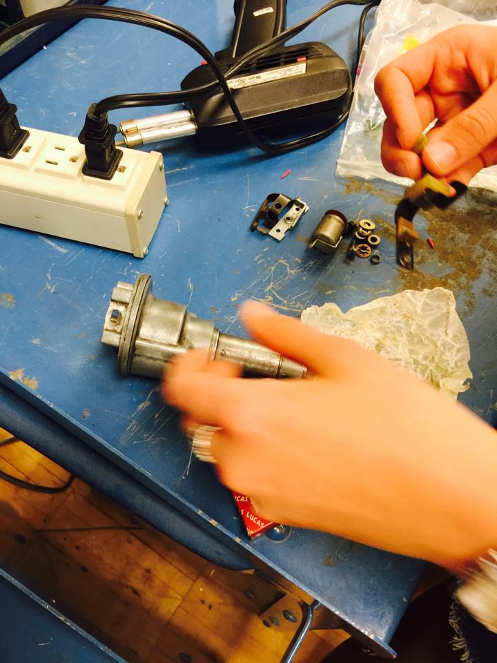
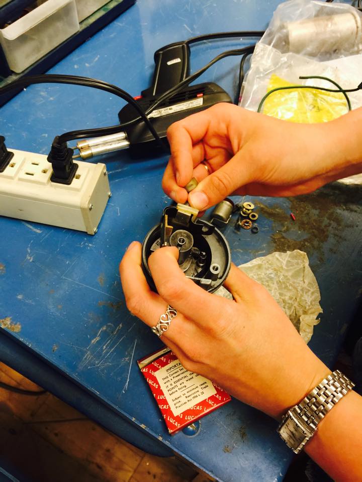
We faced a number of difficulties while assembling the points as well as the distributor.
One problem stemmed from the fact that the camshaft of the distributor actually came from an older spare part that we had lying around in the shop. We had to use this one instead of the original one due to the fact that the original one had some broken parts. The camshaft that we used did not have an optimal fit for the distributor casing, which warranted us to shave the sides of the camshaft in order to have it spin snugly within the whole distributor assembly.
Furthermore, the points themselves needed some attention. Because we replaced the original points with new spare parts, there were bound to be some incompatibility. We had to shave some material off the wooden lever attached to the points so that the gap between them could be rendered smaller.
The Distributor and the Centrifugal Advance Mechanism
Within the distributor assembly, there are springs and weights that control the timing of the ignition. At higher RPMs, these springs and weights allow the ignition to be advanced slightly so that ignition occurs right before top dead center.
This mechanism is called the centrifugal advance mechanism. The “centrifugal” part stems from the fact that the ignition is advanced as the centrifugal force is increased; that is, when the camshaft is spinning faster. This allows the springs to stretch and weights to spread out more, rotating the platform attached to the camshaft so that the advance can occur.
Such an assembly is desirable since at higher RPMs, it is better to have the ignition happen right before the piston is at TDC.
The Capacitor
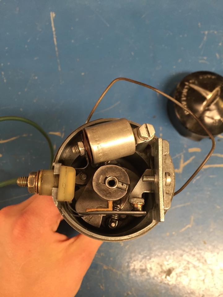
This capacitor that you can see right above the camshaft is actually an essential part of this battery-powered ignition system. Its purpose is to complete an LC circuit with the coil being the inductor.
The coil, capacitor and the contact breakers work in unison in such a fashion:
When the contact breaker (the points) is closed (a closed switch basically), current builds up in the primary winding of the coil. By the time that the contact break opens, enough current has built up in the primary winding.Due to the fact that there is a capacitor (within the distributor assembly) within the circuit downstream from the coil, this creates an LC circuit. Consequently, there is a “back voltage” that travels across the inductor (coils), causing change in electromagnetic field from the primary coil, which then creates a voltage in the secondary coil. Here, the role of the capacitor is to facilitate a stronger change in the electromagnetic field, causing a stronger voltage induction in the secondary coil. This high voltage is then finally used to create a spark within the spark plugs.
The Spark Plugs
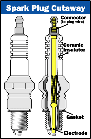
Like we have mentioned multiple times above, the spark plugs are directly involved in the creating the sparks themselves within the ignition system. It achieves such a plug by causing the voltage to “jump the gap.” As you can see in the diagram above, a spark plug as an electrode that is insulated by the ceramic insulator. The ceramic insulator ensures that the the spark happens at that little gap between the electrode and the and the tip of the spark plug. This spark is what is used to ignite the air/fuel mixture within the piston cylinders.
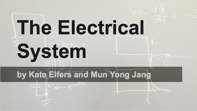
The Headlight
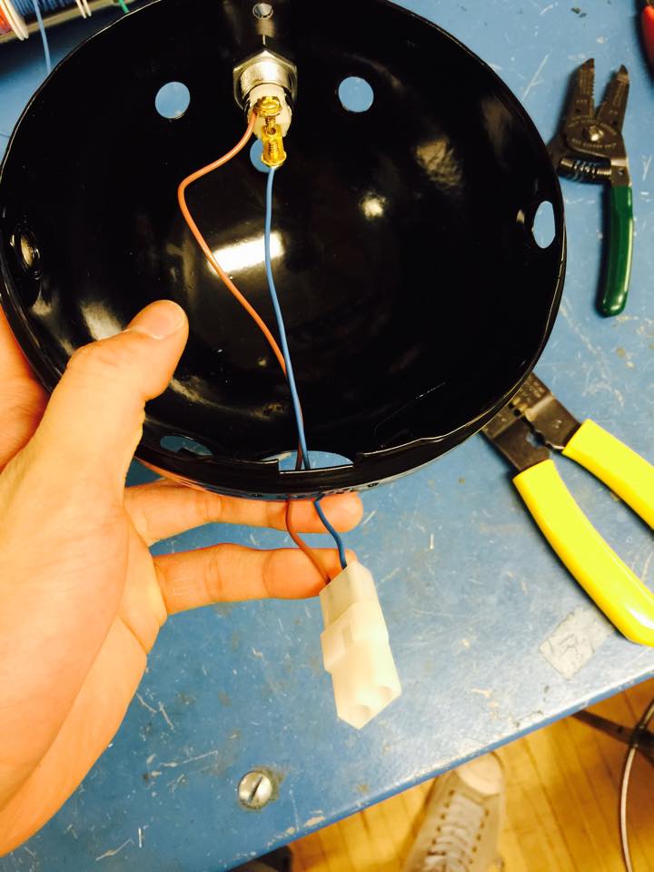
This is how we inserted the switch into the circuitry- in the headlamp. We used connectors so that we can connect and disconnect it easily from the wiring harness. This allowed for easier handling of the headlamp since we could take it on and off at our request.
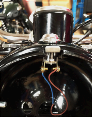
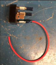
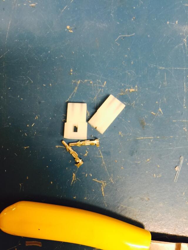
Some Techniques We Used: Soldering

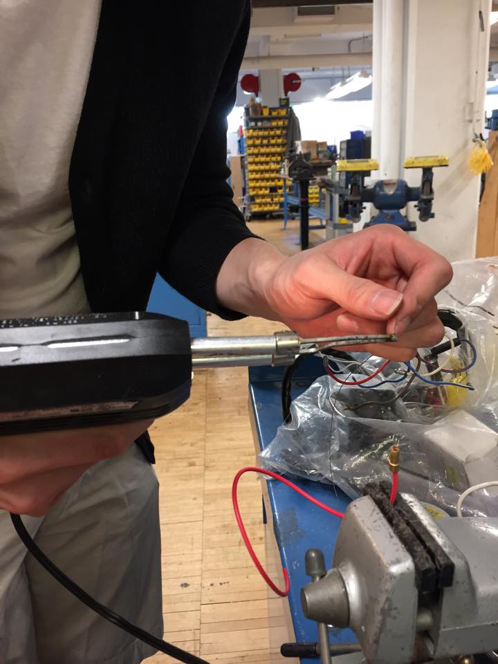
We largely soldered so that we could attach bullet connectors to wire ends so that we can make connections that can be easily connected and disconnected.
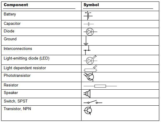
Because we were complete neophytes, we had to learn how to read circuit diagrams from scratch. Though we didn’t encounter all those symbols, we had to learn what most of them represented.