Team members: Alison Bick and Sherry Li
Week 13 — 5/1/12 & 5/3/12
Completion? YES!!!
On 4/30/12, we drove to the DMV in Lawrenceville to obtain our motorcycle permits. After arriving, realizing Alison did not have her 6 point ID, she drove back to Princeton with Sherry’s phone (GPS). She picked up her passport whilst Sherry took the motorcycle test, and luckily, Alison was able to pick up Sherry’s contacts when Sherry failed the vision test at the DMV. Alison got back to the DMV (after Sherry’s phone died and she had to ask someone for directions) and passed her test as well.
Week 12 — 4/24/12 & 4/26/12
Assembly!
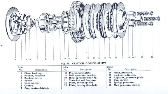
This week we were able to put the clutch back together. Using the manuals, we assembled the larger engine sprocket first. We used our old clutch basket and put the new clutch plates that Glen bought on them. (Glen had adjusted the plates prior to our assembly). We carefully assembled the engine sprocket and used the Allen key to screw the new cup-loaded springs to complete its assembly.
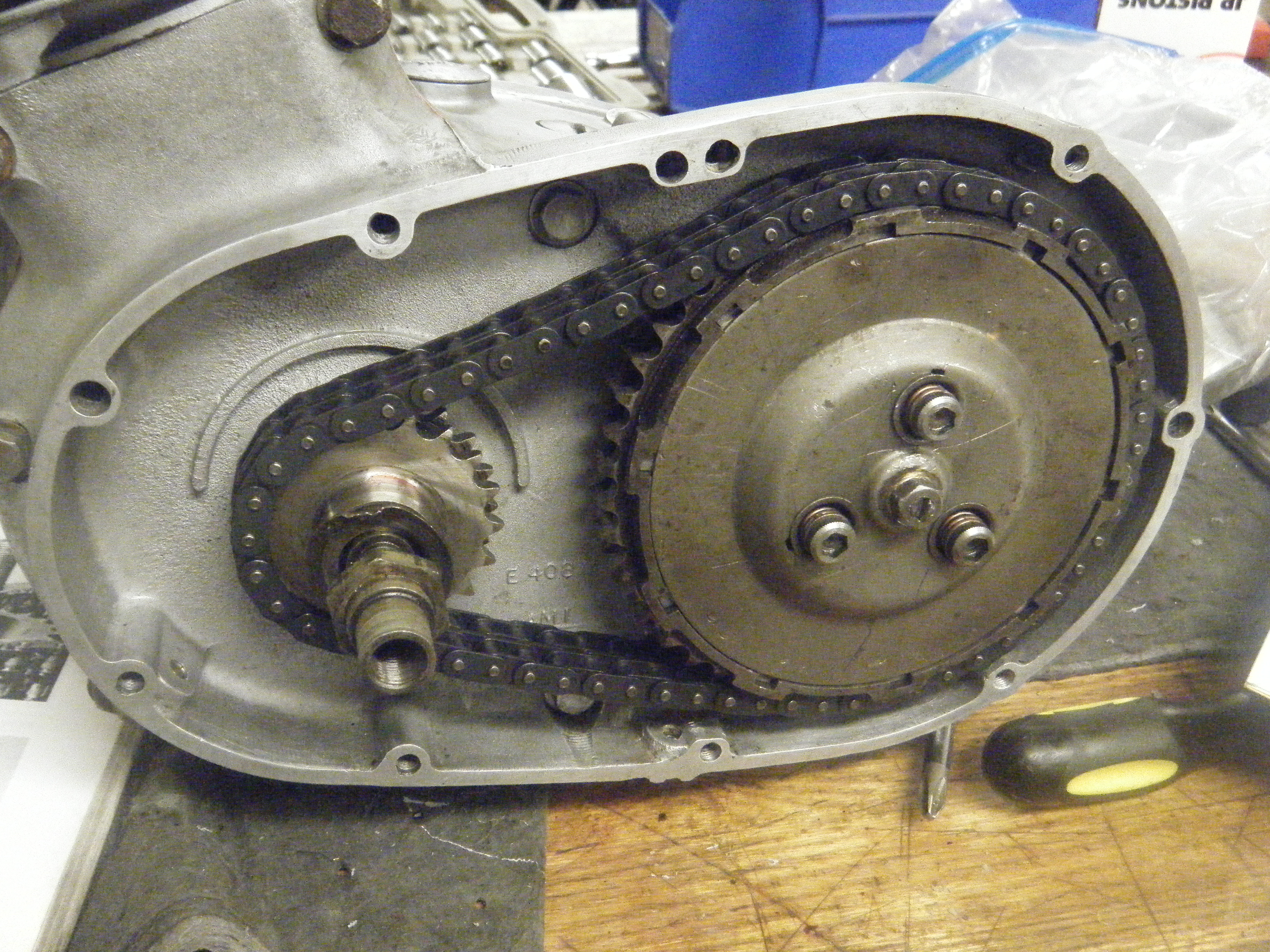
Afterwards, we put it onto the case but realized that we would have to assemble the clutch sprocket, place both of them on at the same time with the primary chain in order to put the chain on.
The clutch sprocket was trickier to assemble. Again, careful adherence to the manuals allowed us to determine which pieces were to be put on first. In the meanwhile, we realized that half of our key was sheared off and stuck in the distance piece of the clutch sprocket. We had put it in in the right keyhole (7 o’clock), but didn’t realize that the key was sheared. We resolved to finish up on Thursday, after Glen made a new key for us.
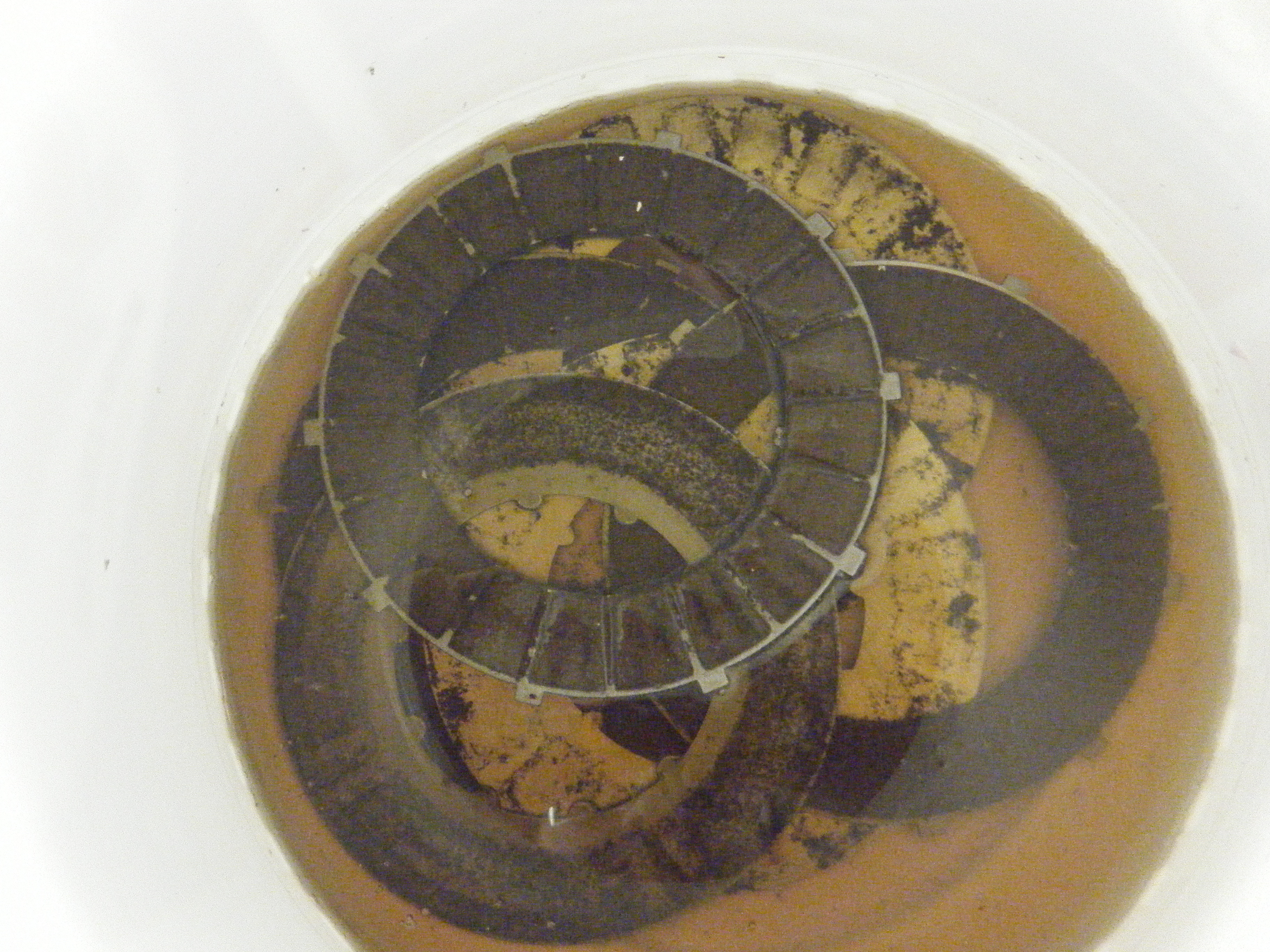
On Thursday, we assembled the clutch sprocket with the new key and replaced the clutch basket because our old one had a broken tooth. Adam helped us clean it before we put it on. We also soaked the plates in oil. Afterwards, we put the clutch cover on.
Overall, we made many errors but luckily, none were fatal. It was a great learning experience as well as a relief to be doing something other than sanding again.
Week 11 — 4/17/12 & 4/19/12
And we conclude the clutch sanding
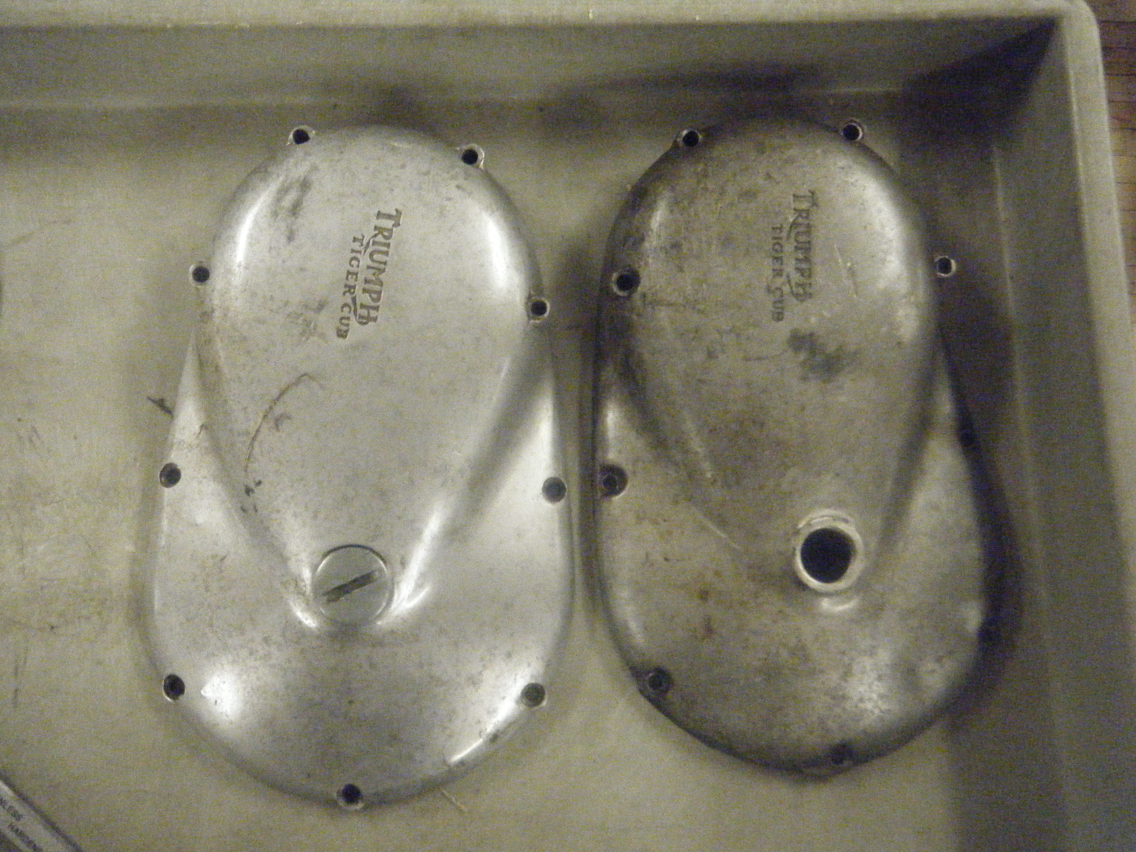
By Week 11 we are getting close to finishing the covers, however it is still does not have the shine of the previous year’s motorcycle. So to take any last roughness of the covers, we finished our sanding in the sink.
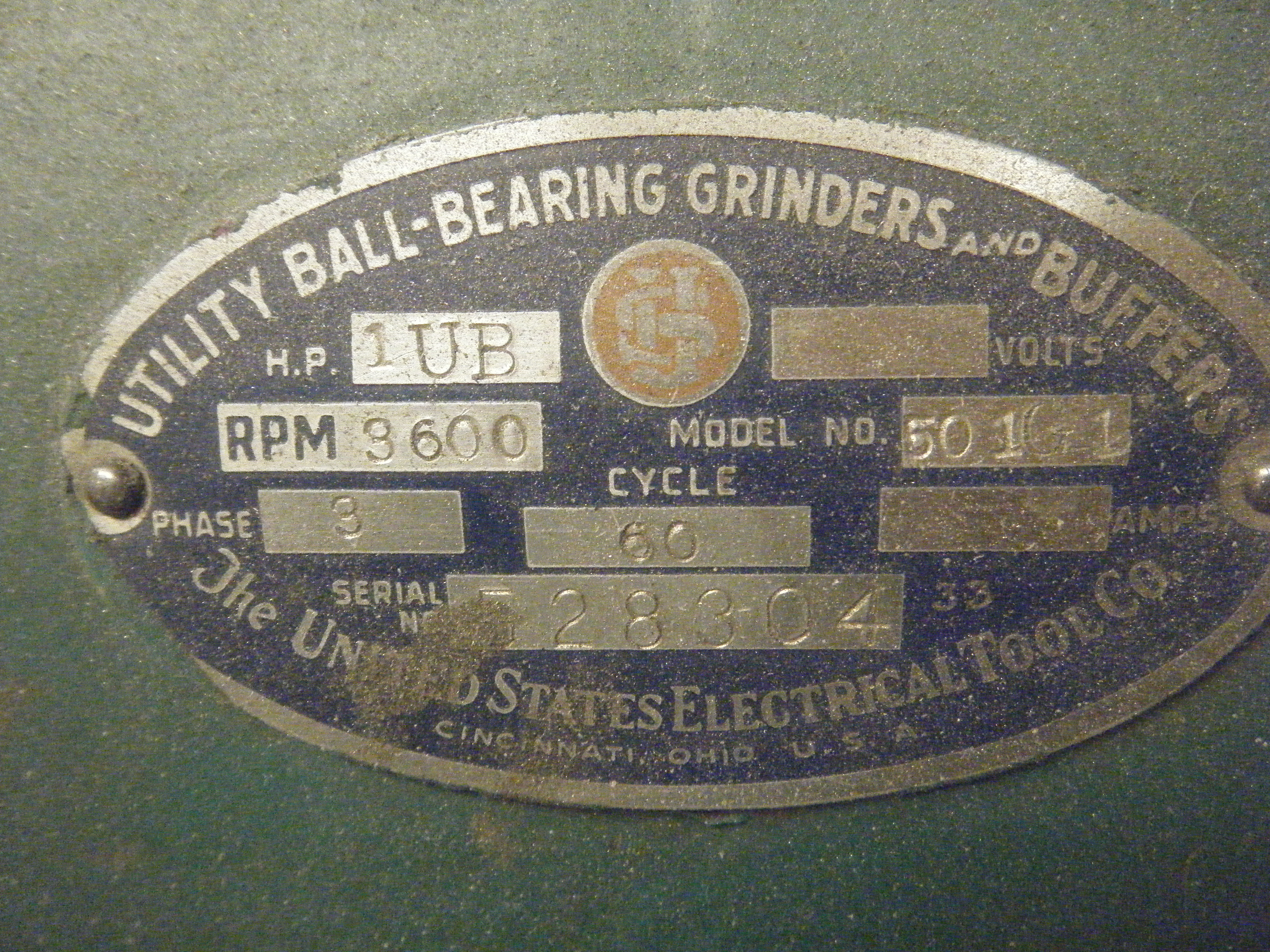
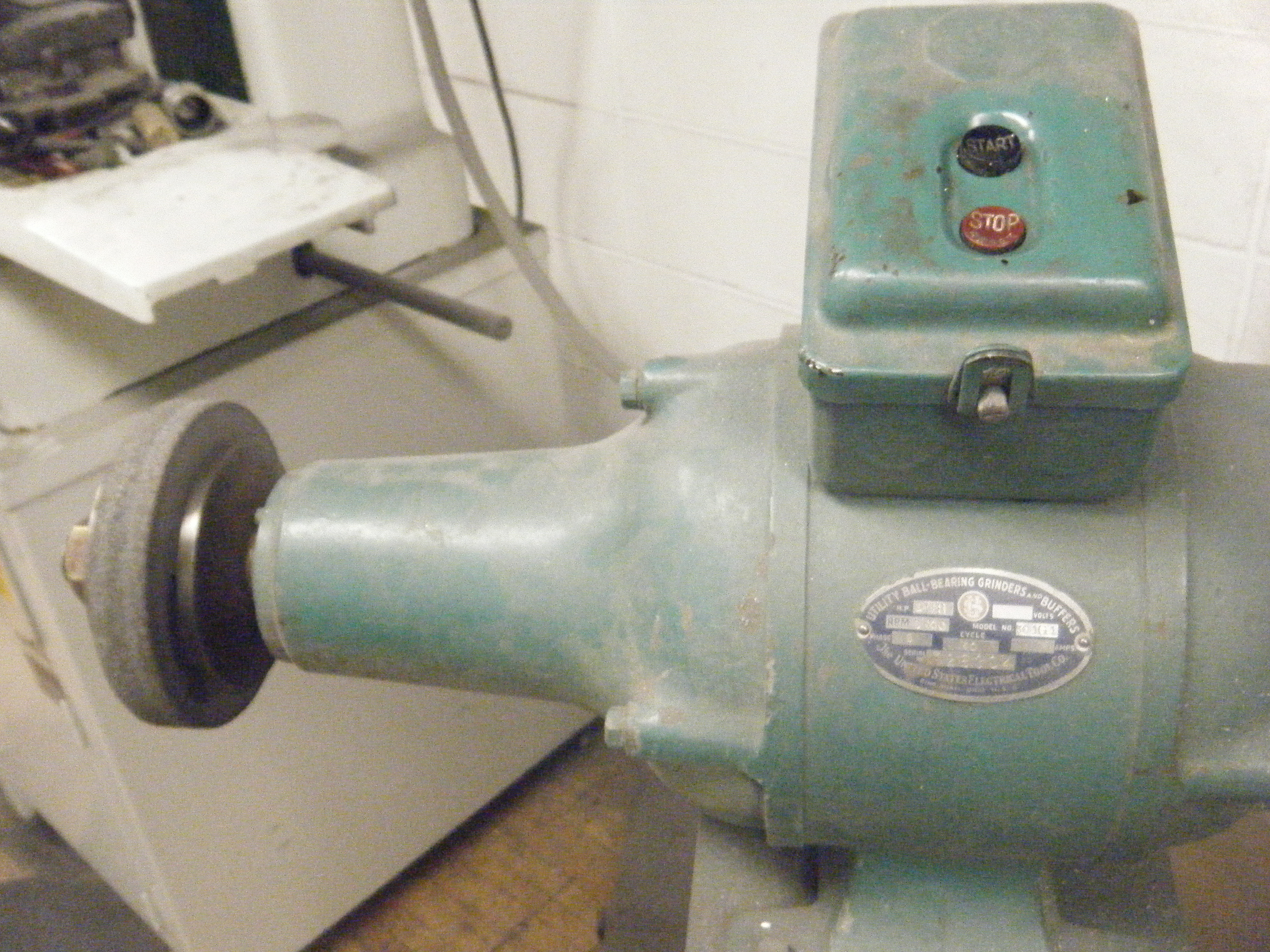
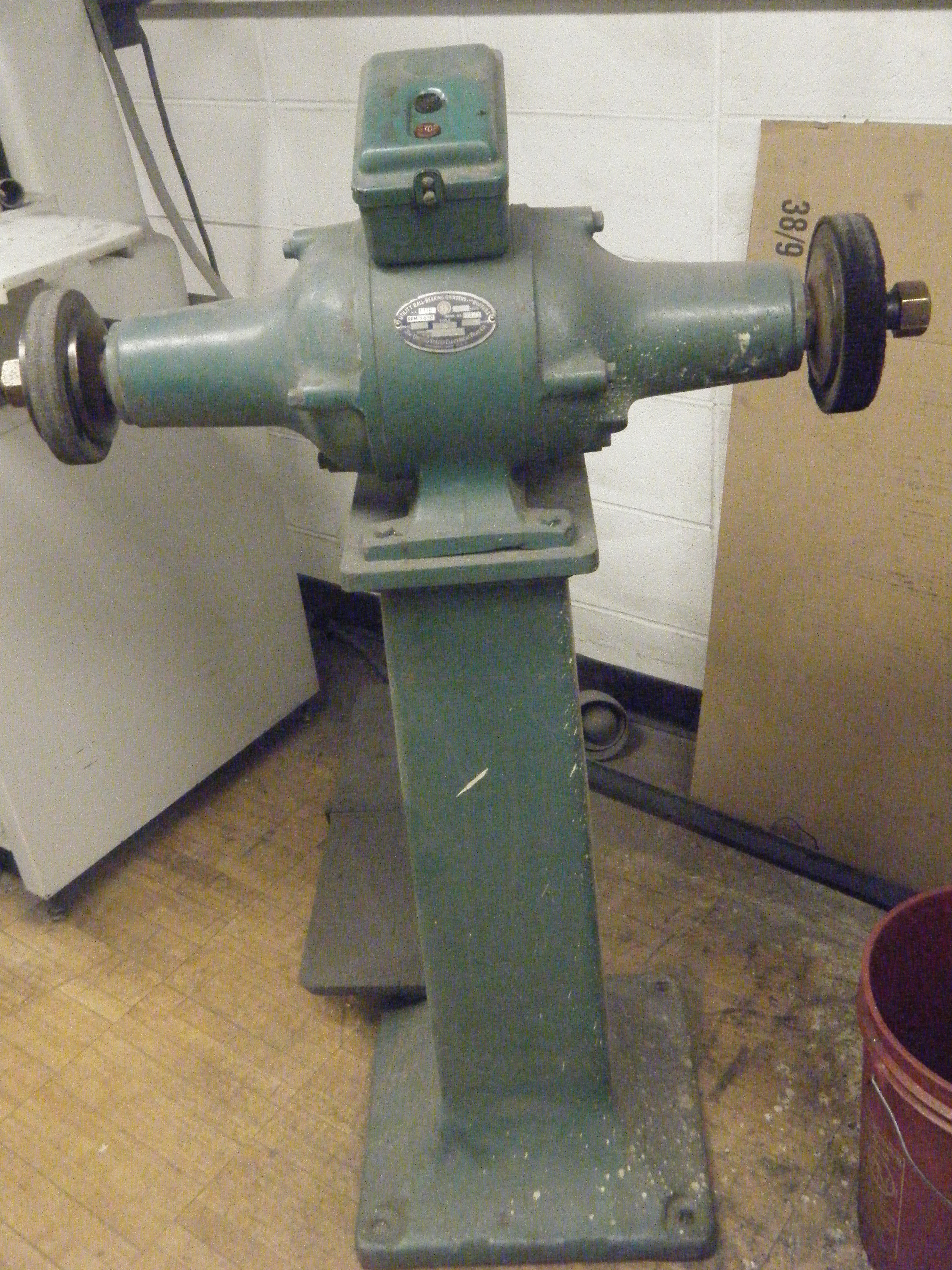
Then, we had Prof. Littman use the Scotch Brightener machine to make it really smooth. Essentially, the machine is a spinning wheel covered in fine grade sand paper. The wheel spins really quickly (3600 rpm) which takes off any final layer of rough metal from the covers.
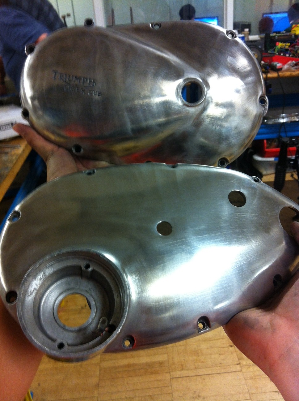
After this, we used a billow sponge and polish to shine the cover. This made the covers really shine and appear smooth to the touch. Glen told us that these covers were much better than last year’s covers 🙂 See how they came out!!!
Week 10 — 4/10/12 & 4/12/12
Continuation
We continued our journey in sanding, this time venturing out into the wild (read: E-quad courtyard). Here, Alison showed Sherry the blister on her thumb – popped and painful from sanding so diligently. By now, we had invested our energies and efforts into this sanding project – it became a matter of pride and honor.
Even so, we wondered that there must be a machine that could perform this task. Alas, we learned that the surface of human fingers could do a better job than an inflexible and hard sanding surface.
Week 9 — 4/3/12 & 4/5/12
Serious Sanding
This week we realized how much work we had to complete on the clutch covers. Alison’s cover was not too damaged, but Sherry’s cover had huge gashes in it. In fact, it was so bad that John did not think Sherry would be able to remove all of the deep dents. So, to better assist us in our attempt to sand the covers we requested lower grade, super course sand paper. In our search, we found 40, 180, 360, 400, 600 grade. Below is a picture of the different sand papers we used.
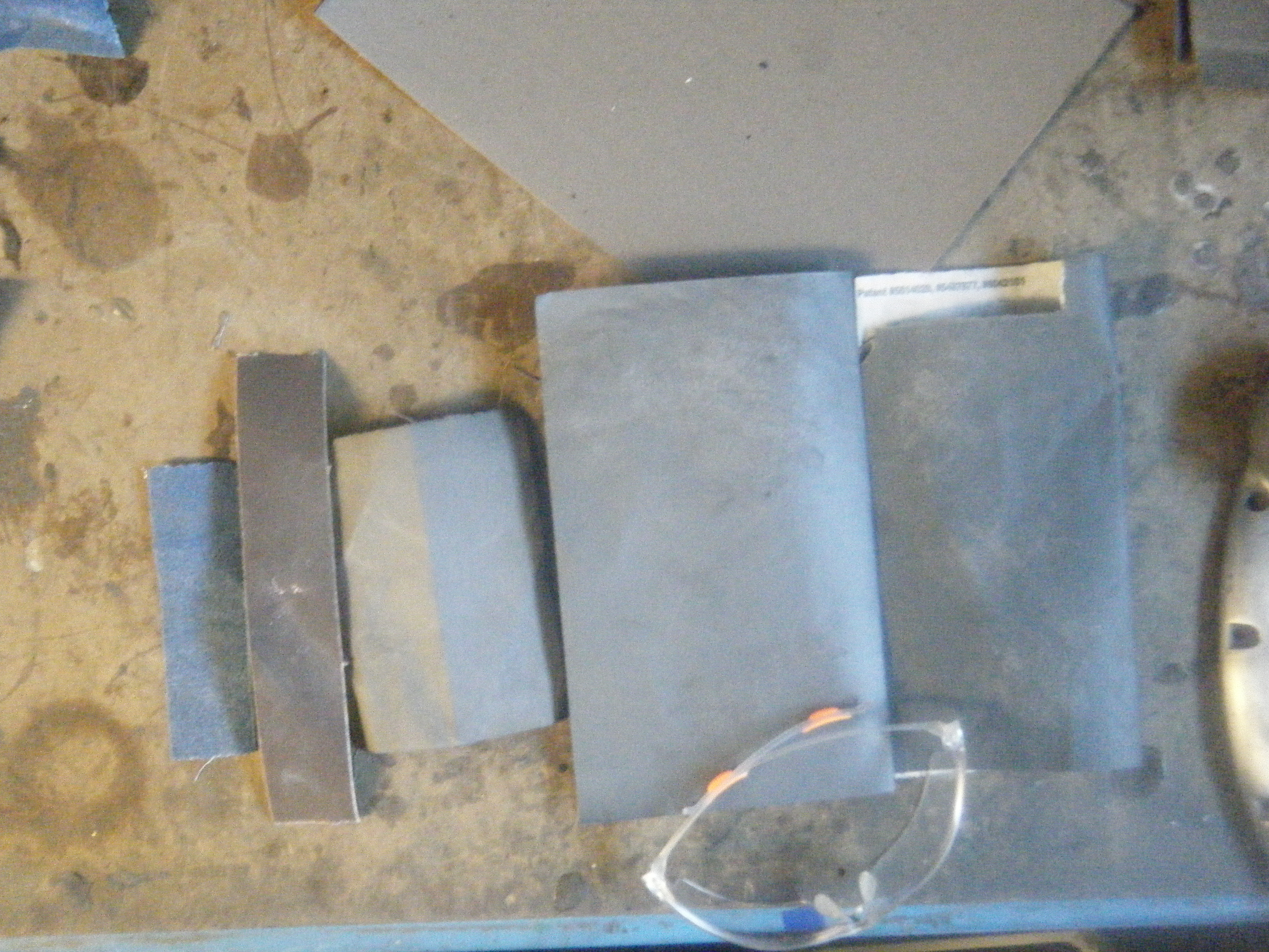
To get the smoothest results for the cover first use the lowest grade sand paper, then move to a higher grade sand paper. As the grade number used increases the cover becomes smoother.
By the end of this week, we noticed considerable improvements in the cover; many of the dents were gone or faded. However, now the cover seemed rough and uneven, so for next week, we have to start evening out the surface, and then use the finer grades (higher numbers) to give them a smooth finish.
We also made our presentation on Thursday.
Size: 44.8M bytes Modified: 1 May 2012, 16:17
Week 8 — 3/27/12 & 3/29/12
Beginning to sand
Since our disassembly of the clutch was finished, we sought out other tasks. These included sanding the headlight piece, which was a half of a hollow sphere.
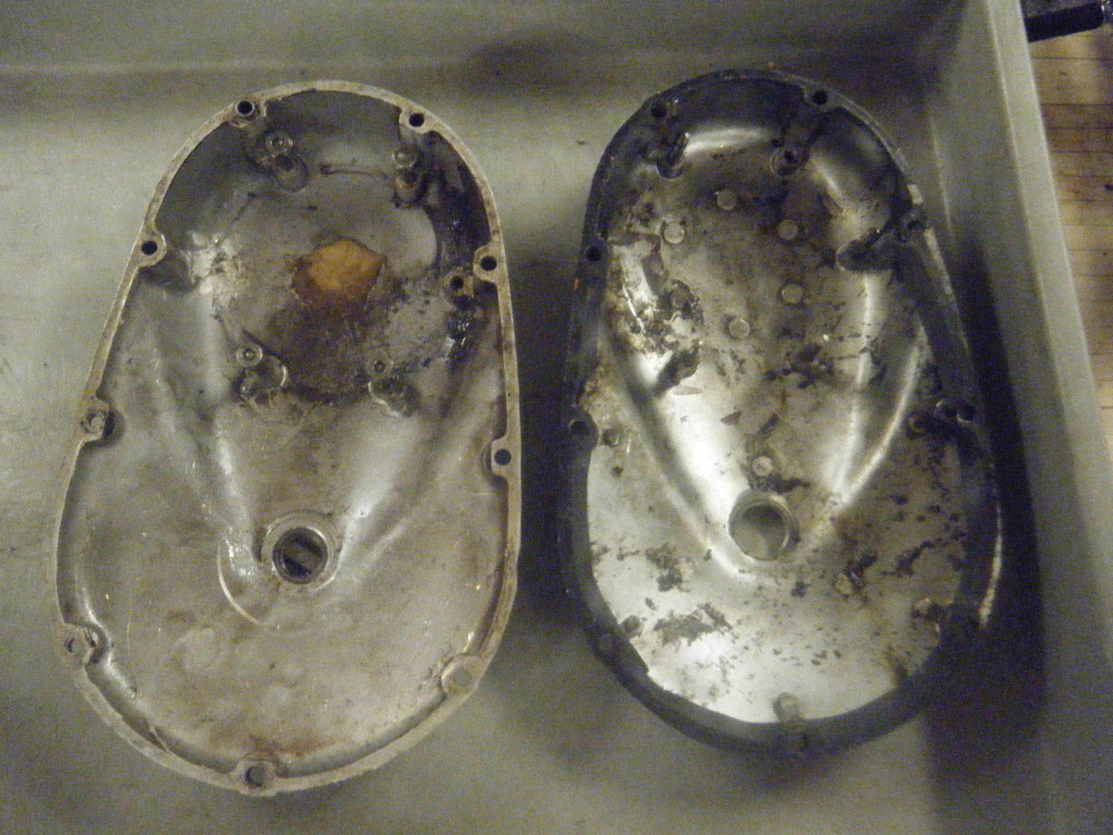
Then we picked up a bigger task, which consumed a great amount of our time in the class. We each took a cover: Alison took the transmission cover and Sherry took the clutch cover. These cases contained many deep scratches and cuts that needed to be sanded out. The clutch cover from the original bike wasn’t in good enough condition to use again, as there was a splotch of glue on the inside. Chris took us to the storage shed and we picked out another clutch case that matched ours.
The pictures of the covers before sanding are shown below:
After sanding minimally with grade 240 sandpaper, we quickly moved on to higher grades. Professor Littman explained to us that this was not a simple task, that it would take us weeks to do it right. Even though we complained, we got down to business.

Week 7 — Spring Break
We did nothing.
Week 6 — 3/15/12
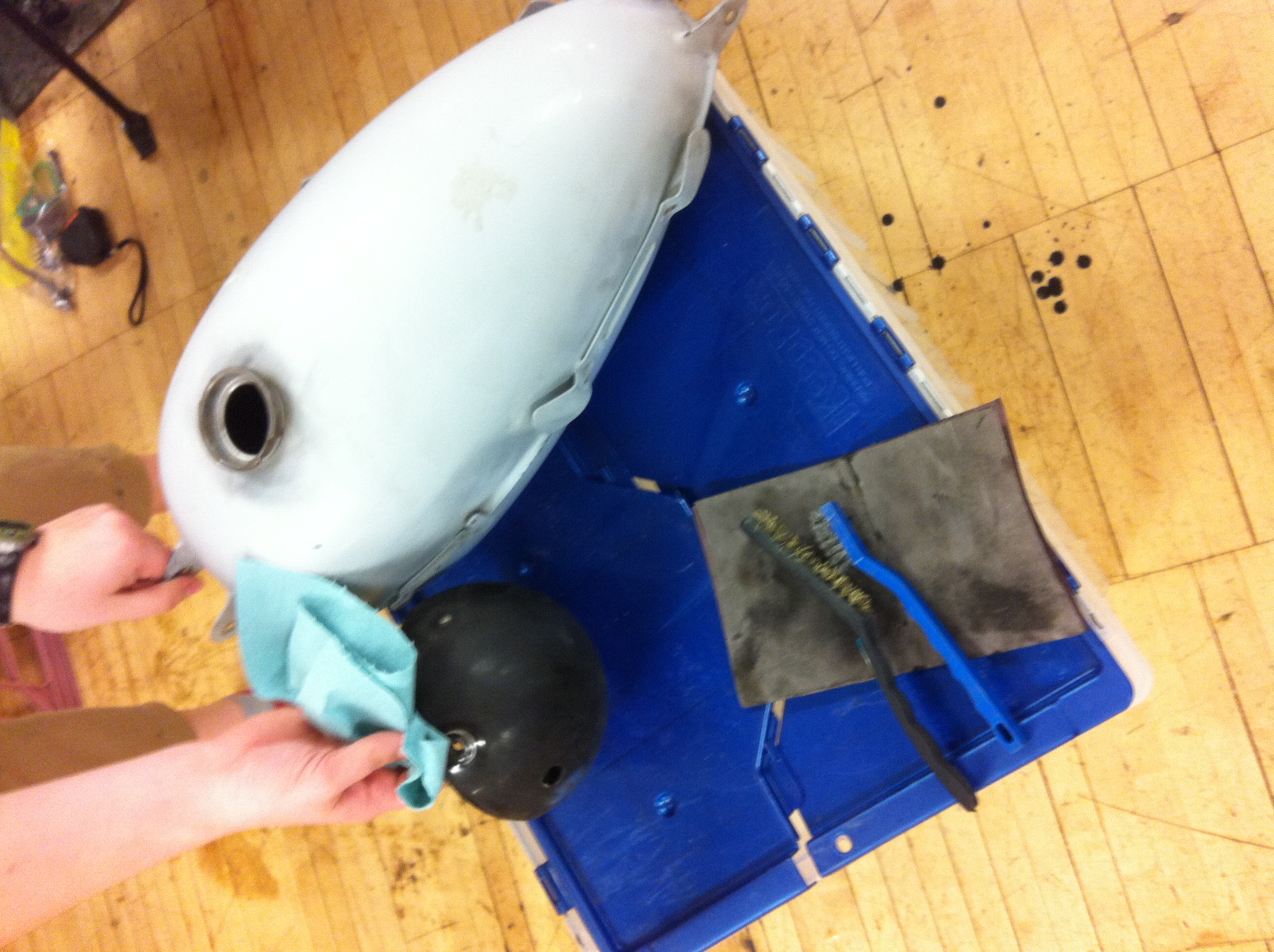
Drove the Model T and Cleaned the Gas Tank & Head Light Case
Today we got to drive the Model T!!!!
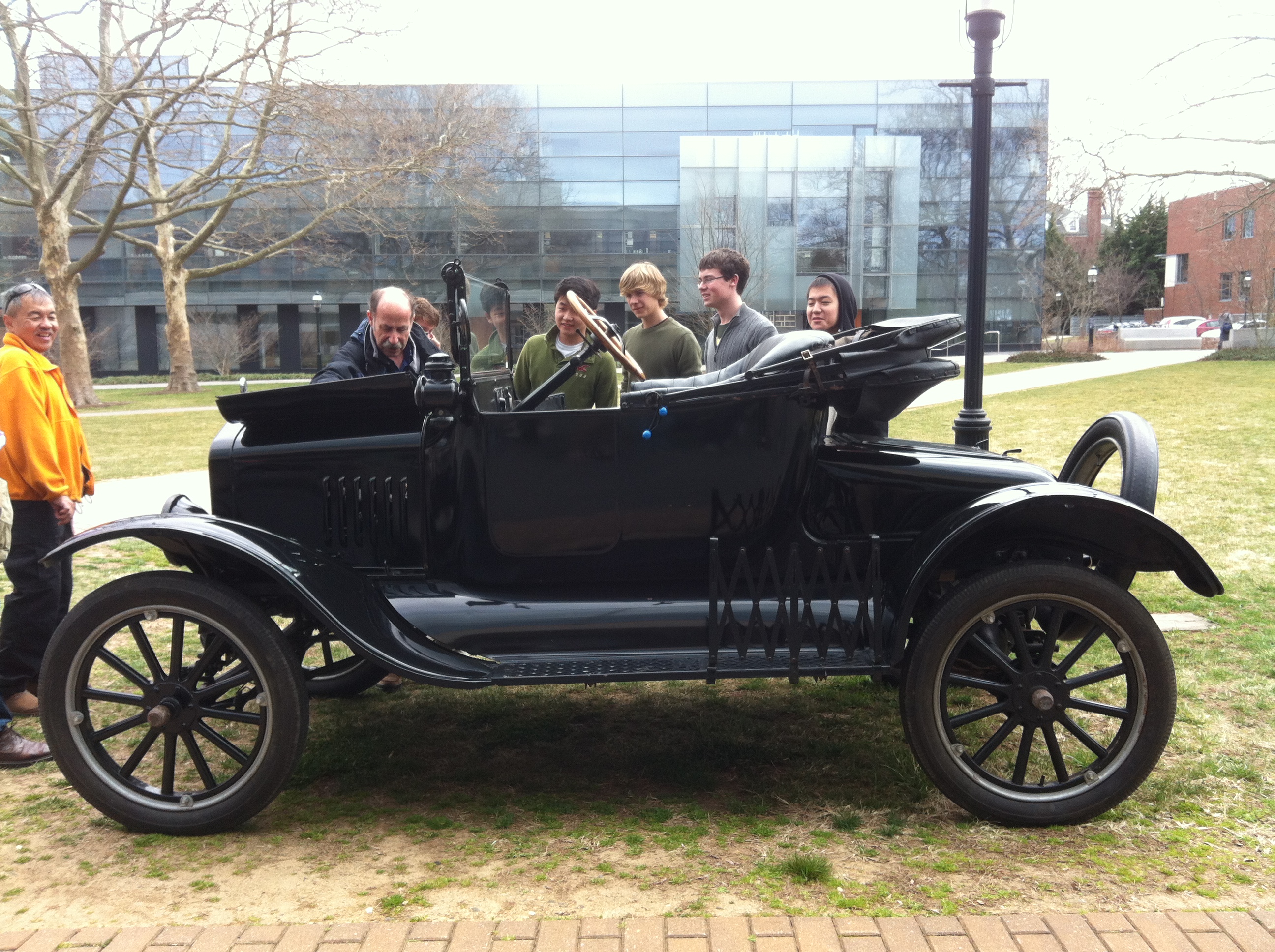
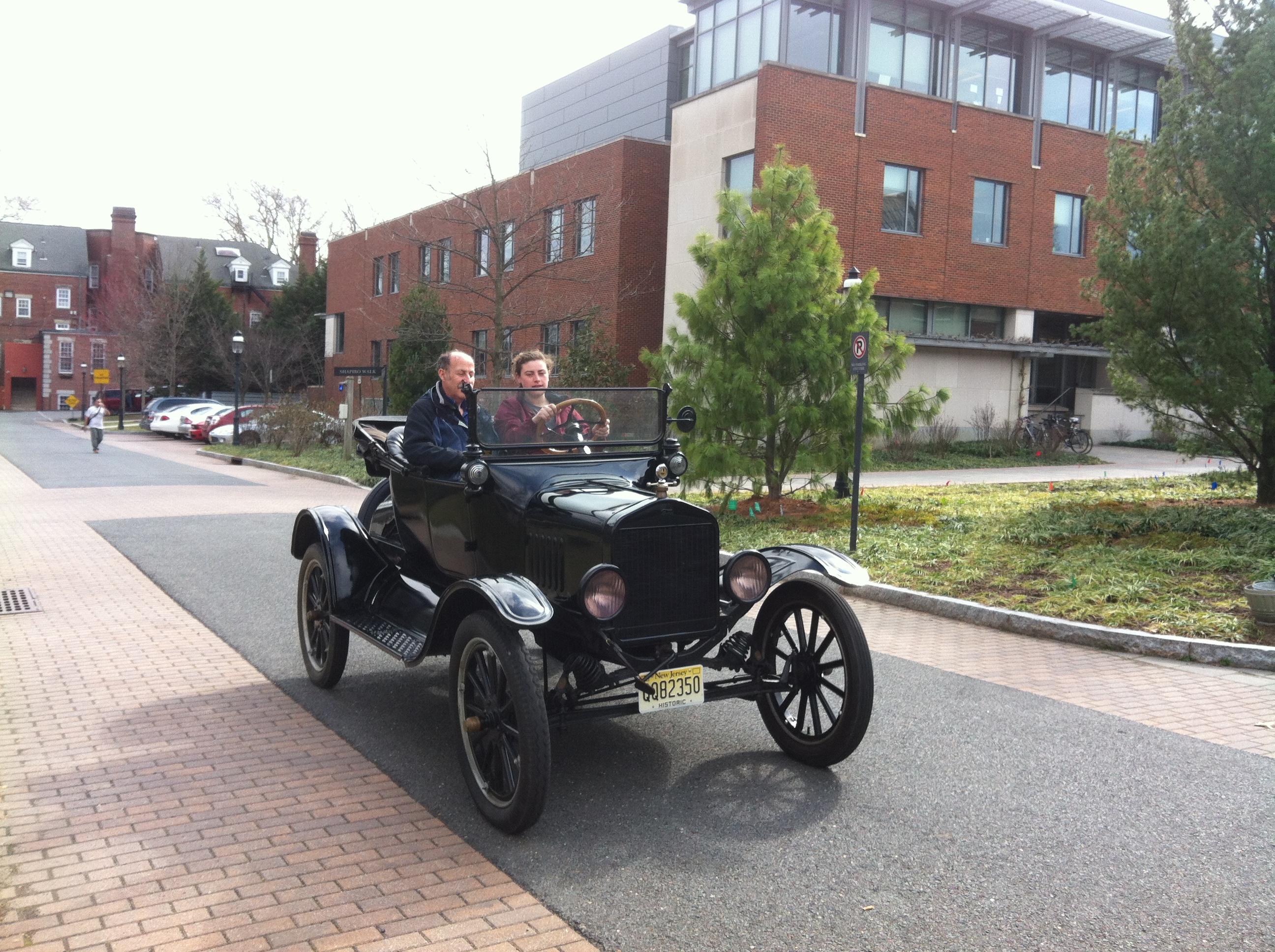
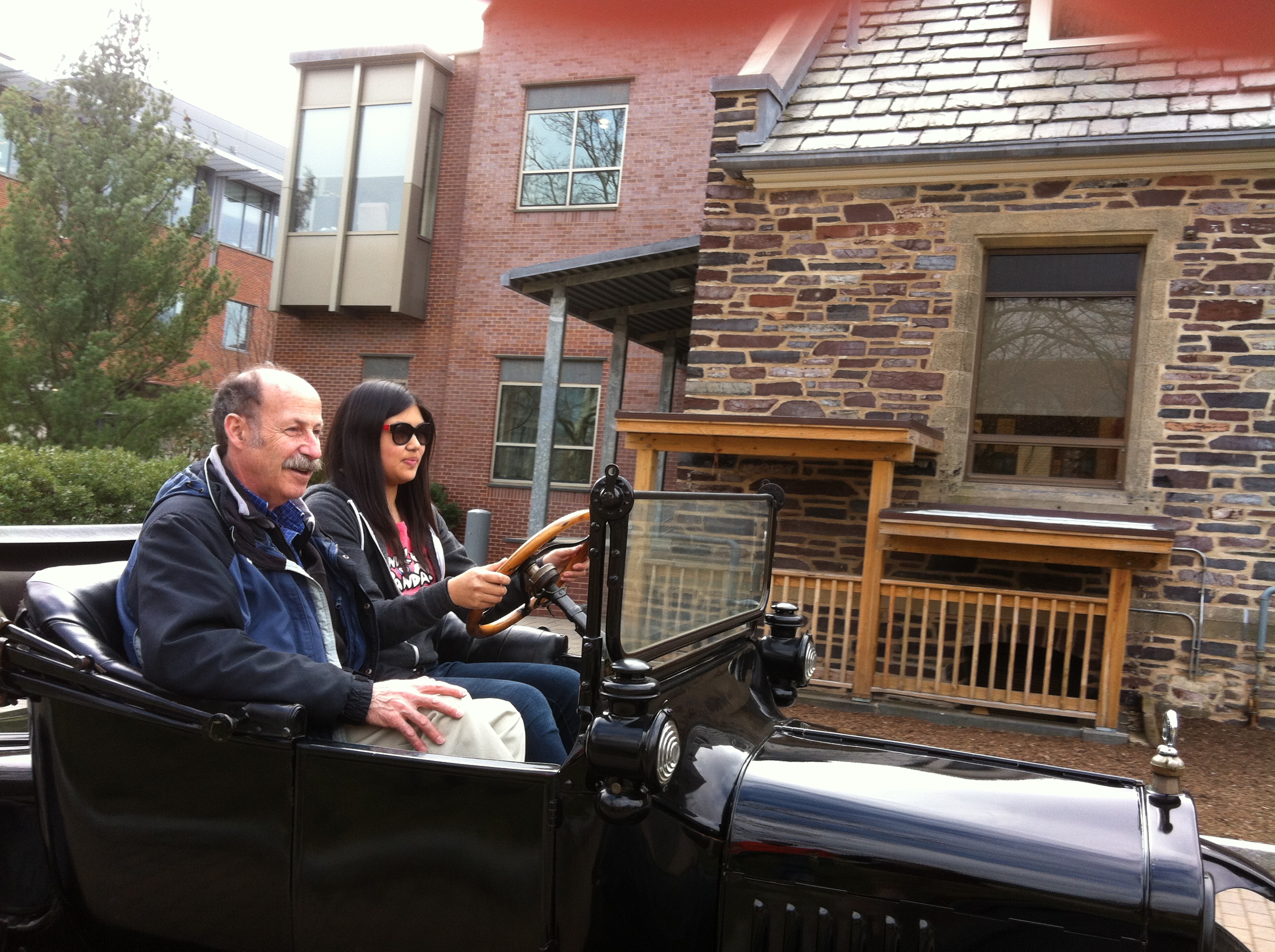
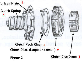
Prof. Littman explained that the Model T transmission is very similar to our Tiger Cub transmission so we decided to do a little research about the clutch and how it is similar to ours. Below is a picture of the Model T clutch. When the spring is pushed to its full pressure, all the small and large discs are fully engaged – this is characteristic of high speed gear. In order to reach high gear, the emergency handbrake must be pushed to the furthest position. (http://www.modeltcentral.com/transmission_animation.html)
Then, in the lab we were preping the gas tank and the head light cover for painting. Specifically, we were trying to remove all of the rust. We used the wire brush and emory paper to do this. Although this task seems easy, it took a lot of time to make the covers smooth and get rust from hard to reach areas.
Week 5 — 3/8/12
Making measurements and helping the frame group
We decided the best way to proceed with the clutch inspection was to measure the different parts. We used The Triumph Workshop Inspection Manual as a reference. These were our findings:
| Part | Instrument of Measurement | Minimum Acceptable Measurement | Our Measurement | Replace? |
| Pressure Spring 1 | Ruler | 1.656 inches | 1.5 Inches | Yes |
| Pressure Spring 2 | Ruler | 1.656 inches | 1.5 Inches | Yes |
| Pressure Spring 3 | Ruler | 1.656 inches | –stuck in spring cup, could not measure | Yes |
| Bonded plates With lining | Caliper | 0.125 inch | 0.118 inches | Yes |
| Bonded Plate lining | Caliper | 0.0313 inch | 0.018 inches | Yes |
| Bonded Plate Without lining | Caliper | 0.0625 inch | 0.109 | Yes |
| Flat Plates Width | Caliper | — | .069 inches | Maybe |
Additionally, we examined the sprockets and plates in a qualitative manner. We found that the ends of the teeth of the clutch and engine sprocket were a little rounded. Also, we examined the plain plates for flatness and stickiness. They were flat, but a little sticky.
After the inspection, we helped the frame group by measuring the dimensions of the forks (the piece that connects the front wheel and axle to the frame). Then, Glenn used the dimensions to model a cap in CAD. Glenn explained to us why he arranged the cap’s dimensions the way he did, adjusting for tightness and thickness.

When we showed Glenn our measurements and told him our examinations / observations, he told us that he will be making a new gasket out of gasket paper. A gasket is essentially a seal used in between two surfaces, often to prevent leakage or to fill out any irregularities between two surfaces. He showed us the machine that would print the gasket, as well as a 3D printer.
Parts inspection and painting
Today was a relatively light day. We basically inspected all of the parts of the clutch and got an idea about which parts we need to replace. The parts that we initially decided to replace are plates and the primary chain.
Additionally, Chris showed us and the frame group the ABC’s of painting. He stressed that it is more of an art form – we need to start spraying off the piece and then across to apply an even coat of paint. Further, it is important to try to minimize running of the paint.
Week 4 — 3/1/12
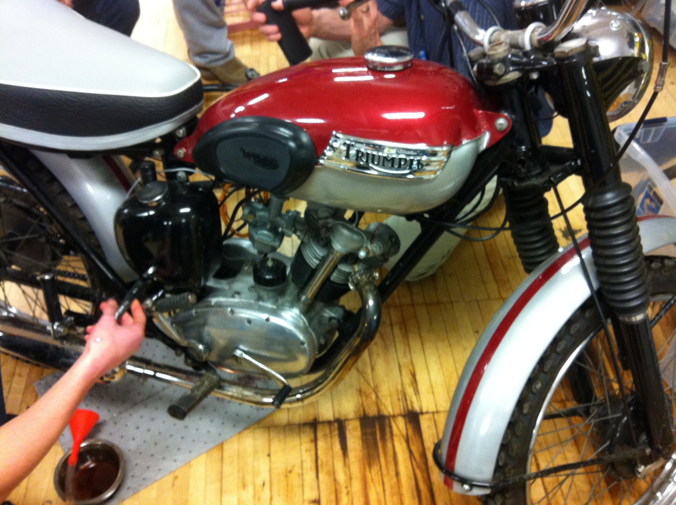
Working on Tiger Cub ’62
Today we took a break from working the clutch by assisting John who is representing his year and trying to fix the Tiger Cub ’62 – there is a vibration in the engine. In order to make a diagnosis, John tried to remove the engine from the rest of the motorcycle. This is a more difficult task than it sounds, for two main reasons.
First, we had to work around the frame and other built in parts of the motorcycle, such as the chain. To that end, when we were detaching screws some of the tools were limited in movement, so it took a long time to remove the necessary parts. Additionally, we had to find crafty ways to access the screws we needed to remove.
Second, the tools in the shop were not organized or in the correct locations. At one point during the day when we needed an Allen key (wrench), there were none in the cabinet. Finally, John found a container full of them, however they were loose, not in a set. So then we spent a little under ten minutes looking through the loose Allen keys, which were also not well labeled. It was upsetting that this took so long, because it is preventable. (Allen keys shown below.)
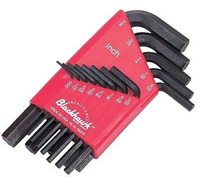
In a similar vein, finding the tools that could accommodate the European design of the Triumph bike was difficult.
Week 4 — 2/28/12
Calculations
How fast can the motorcycle go?
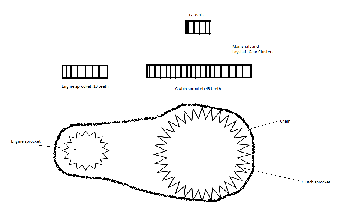
6500 rpm * 19/48 * 17/48 = 911 rpm <—Speed
911 rpm –> 68 mph (top speed)
What is the gear ratio?
Gear Ratio: <–Crankshaft speed to wheel
(19/48 * 17/48 ) ^ -1 = 7.13 <–Top (4th) gear
***This was verified by the table on page 131 in Triumph Instruction Manual
***Additionally, we found the gear ratio for
Third Gear: 8.60
Second Gear: 13.40
Bottom (1st) Gear: 19.80
Week 3 — 2/23/12
Disassembly Day 2
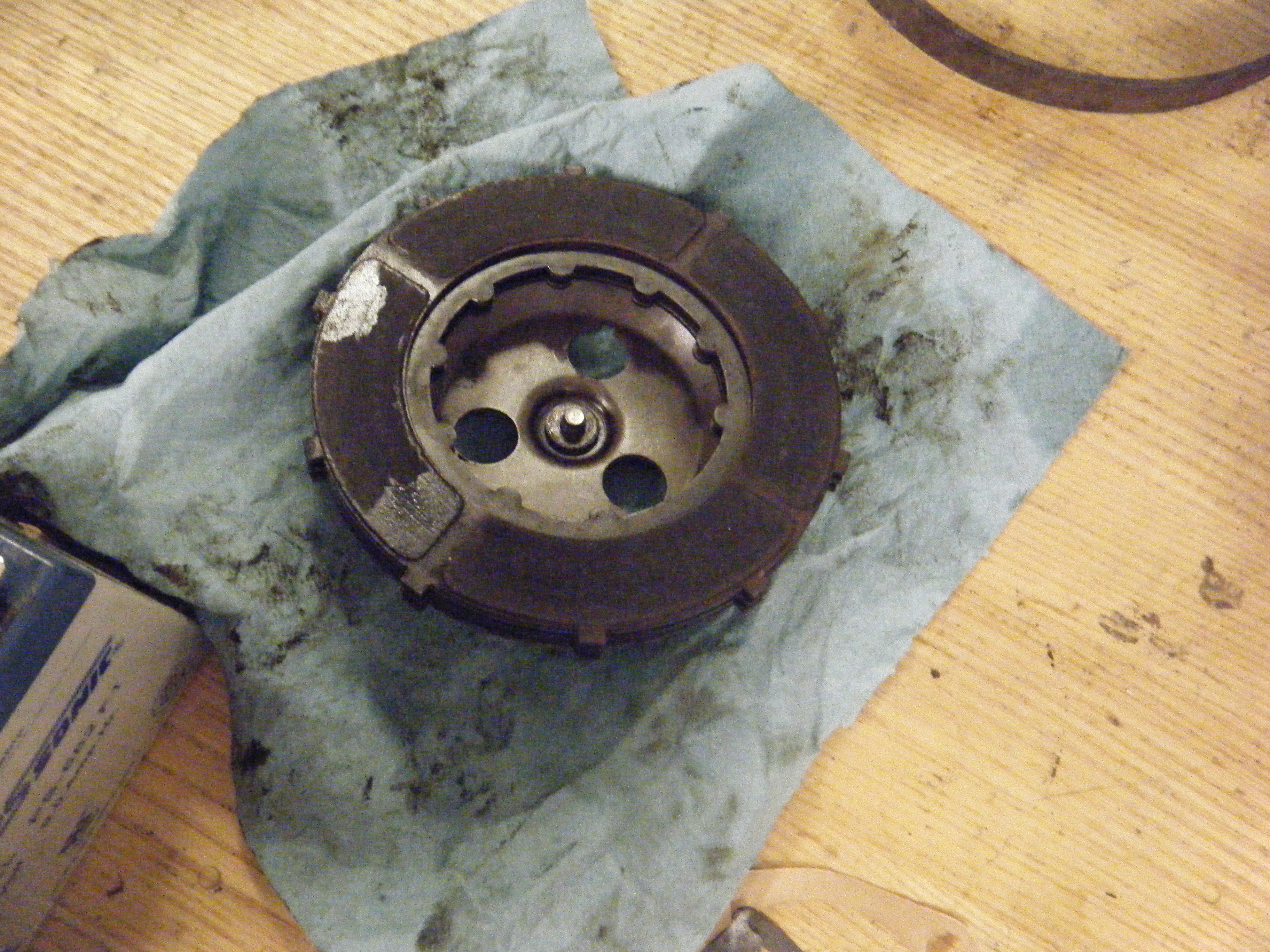
Our last steps in disassembly involved using a strap wrench to hold the clutch basket (to prevent it from slipping) and a ratchet wrench to unscrew a nut. Then we used a puller that Glenn made to remove the clutch basket nut behind the clutch sprocket. This was easy with the puller and allowed us to remove the clutch basket completely, in one piece. We will not be disassembling the clutch basket further, but it contains a center piece with three driving cups, rubber pieces, and a backing plate.
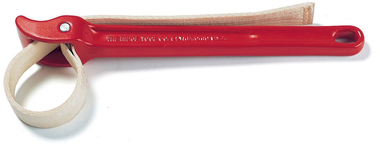
This is a Strap Wrench 🙂
Week 3 — 2/21/12
Disassembly Day 1
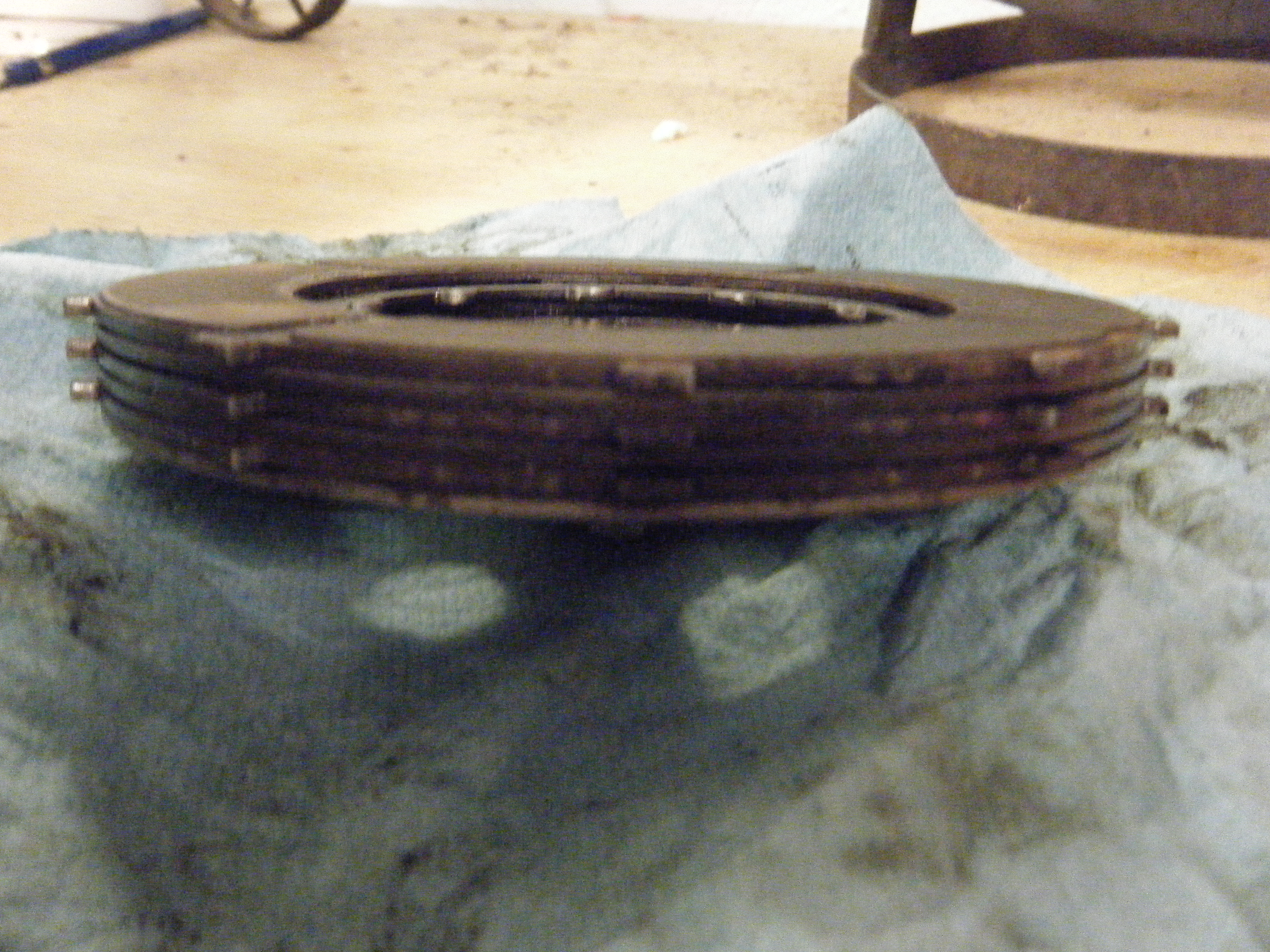
We finally were able to do some work. First we removed the three cups, springs, nuts that protrude from the pressure plate.
The six plates behind the pressure plate should have been separated, but the first five were stuck together. After some resistance, we decided to leave them be and work on disassembling the rest of the clutch.
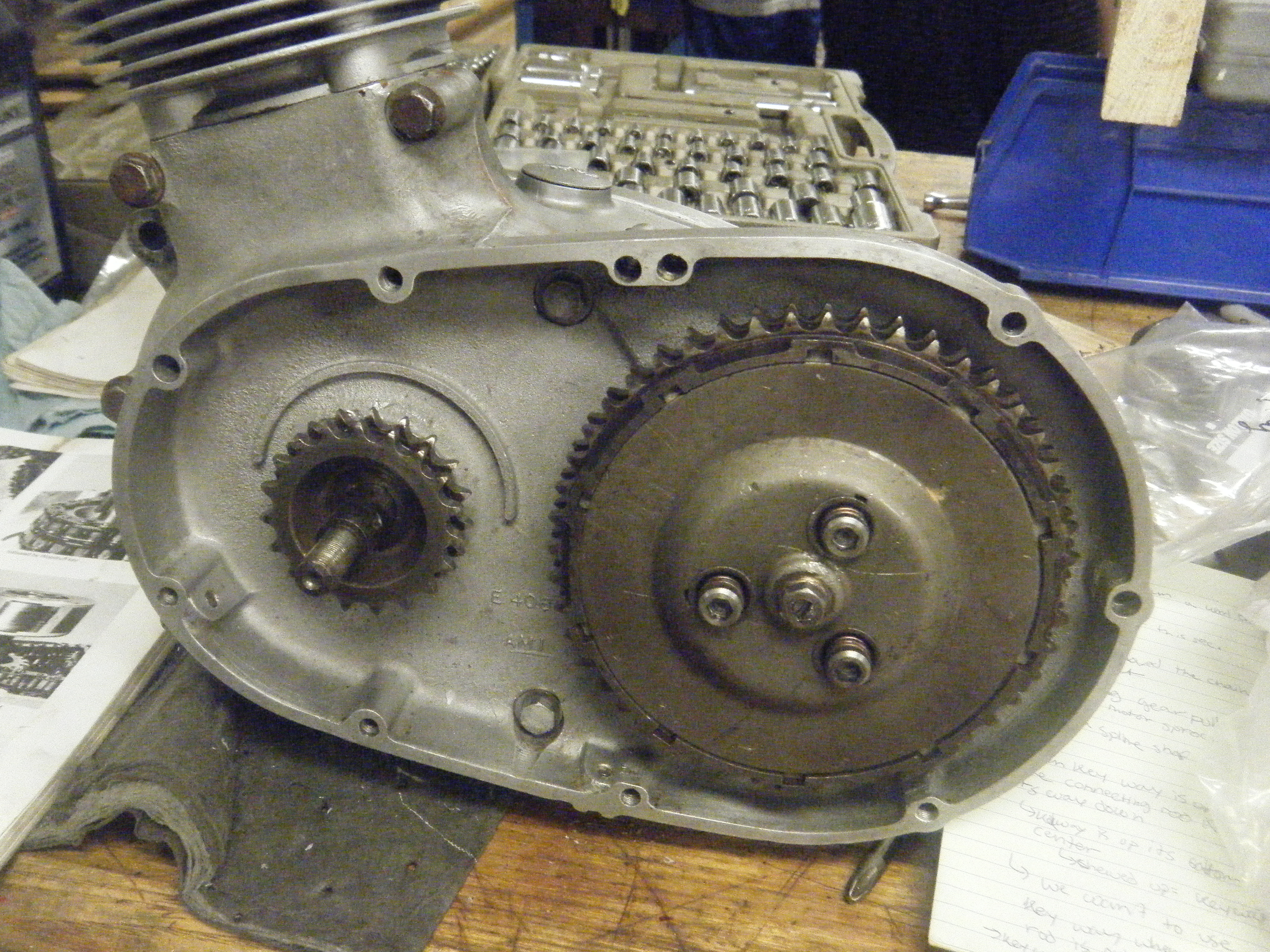
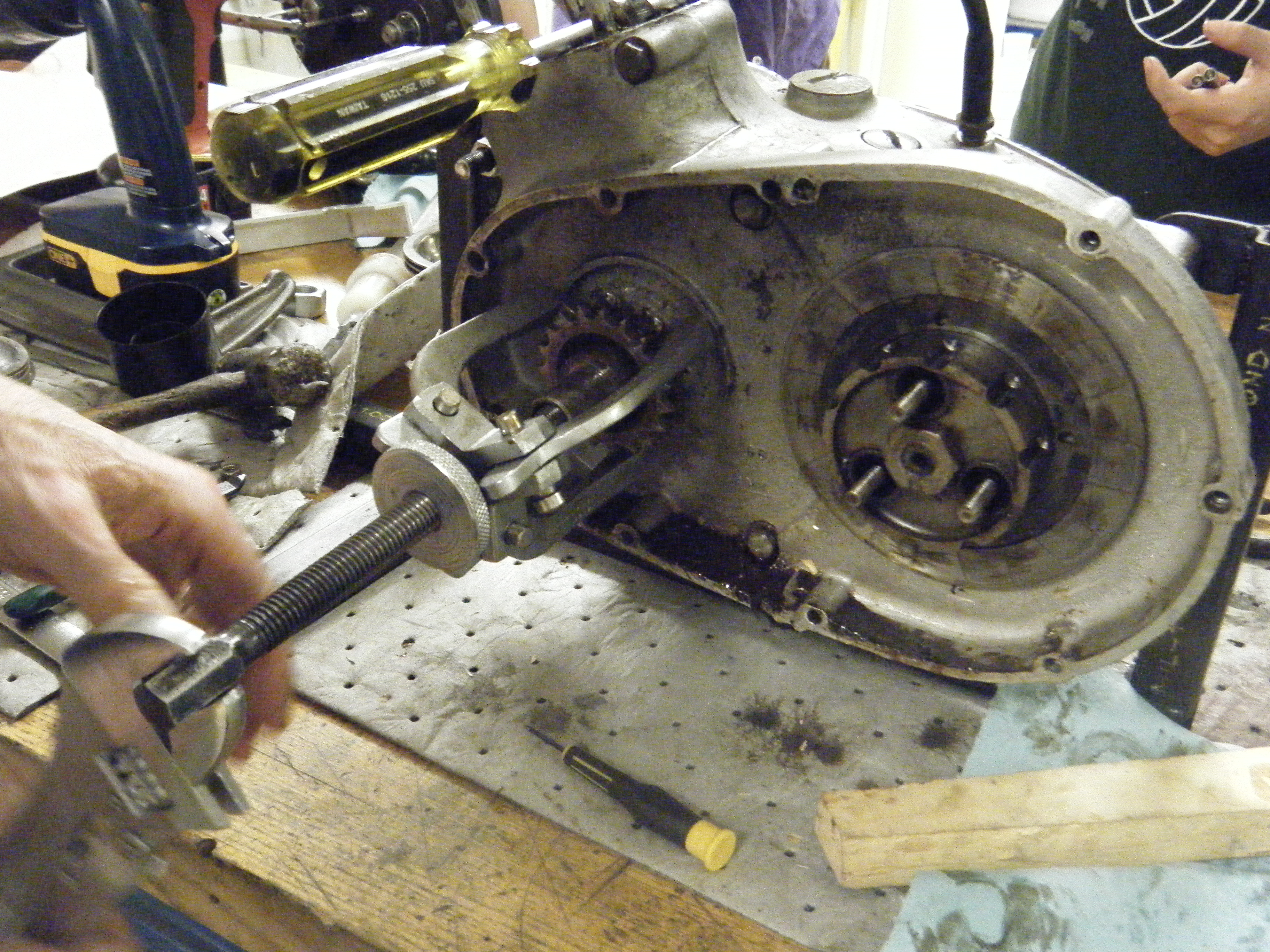
In order to remove the chain, we first had to take off the alternator rotor and the engine sprocket. Using Yield allowed us to unscrew the one sprocket and rotor nut as well as the tab washer. Because the chain is an infinite chain, we had to jam the chain with a wooden block.
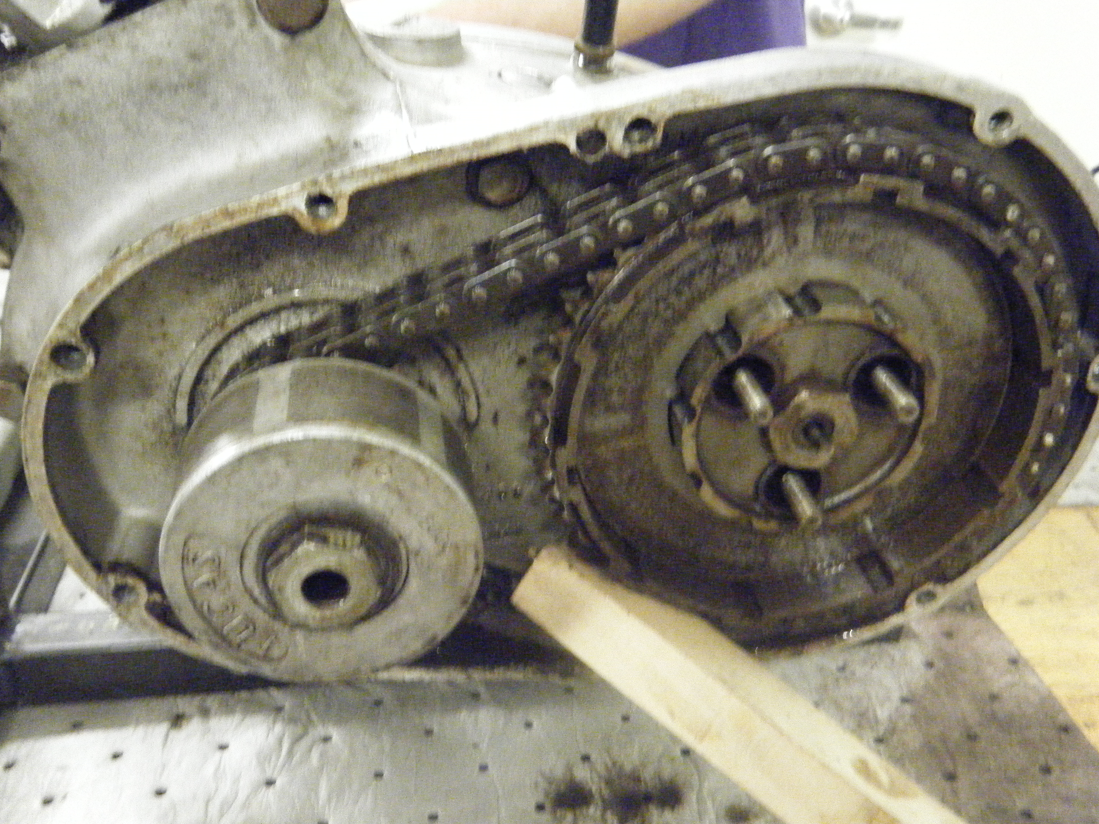
Afterwards, we used a gear puller to remove the magnetic alternator rotor. This revealed the engine sprocket to us, which we used the gear puller to remove as well.
In the center of the engine sprocket was a distance piece. This distance piece had two keyways and a half-moon-shaped key in one of them. These steps required a lot of force – so much that the chain kept slipping and we had to hold the crankcase assembly down.
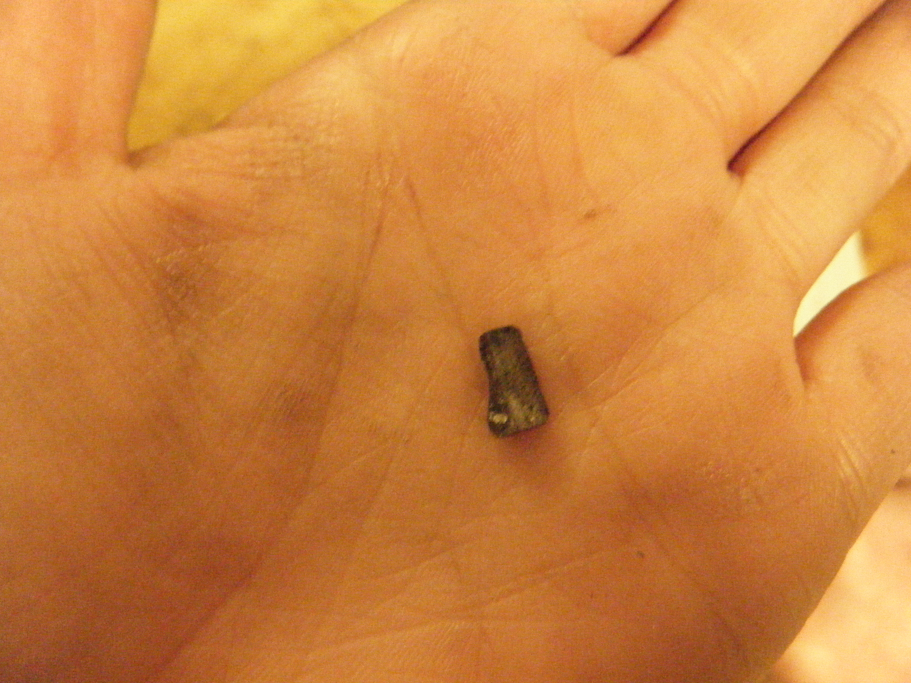
We had to recognize which keyway was the one we needed, and we noted that it was chewed up from use. Just to make sure, though, when the keyway we needed was rotated upwards, the connecting rod in the crankcase assembly was about 30 degrees after top dead center. The connecting rod pumps up and down in an oval-shaped motion in correspondence to the spinning of the chain and sprockets. We also noted that when the keyway we needed was rotated down, the connecting rod was at bottom dead center and hidden in the crankcase assembly.
After the removal of the engine sprocket, we were able to remove the primary chain and the clutch sprocket.
Week 2 — 2/16
Working with clutch model and calculations
Today we examined a model of the clutch and subsequently took it apart. Professor Littman showed us the adjustor, which has a round end that makes contact with a flat surface. When we take apart the clutch of the bike, we could adjust how much this piece protrudes.
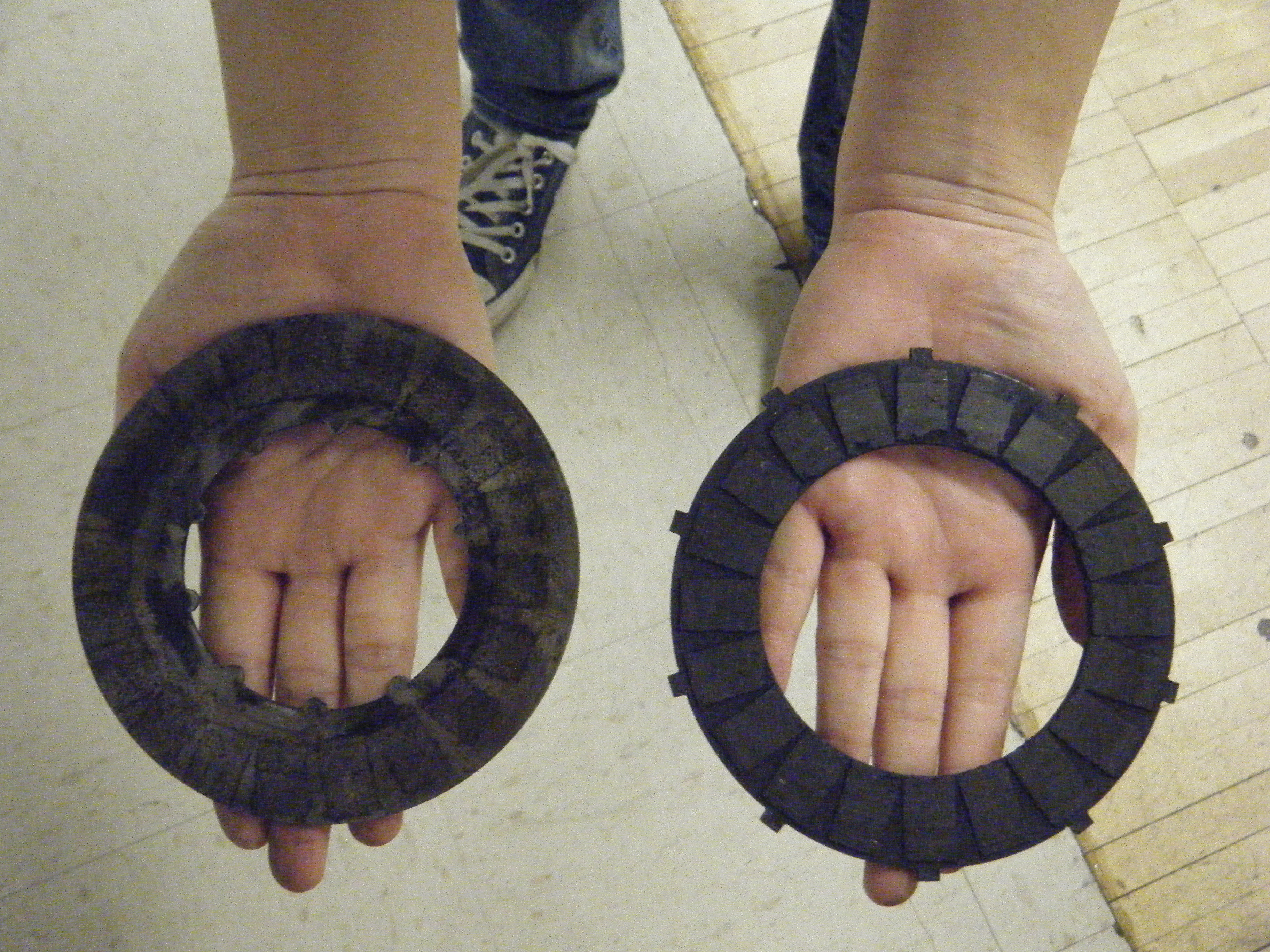
Additionally, we extracted two types of plates. The first type of plate had padding and lugs on the outer diameter, which drive the transmission input shaft. We noticed that these plates had equal spacing between the lugs. We noted that we should order new pads and new plates. We will see when we take the real clutch apart. The second type of plate did not have padding and had lugs on the inner diameter. Of the space between adjacent lugs, one space was not of equal size. These plates are driven by the engine crankshaft.
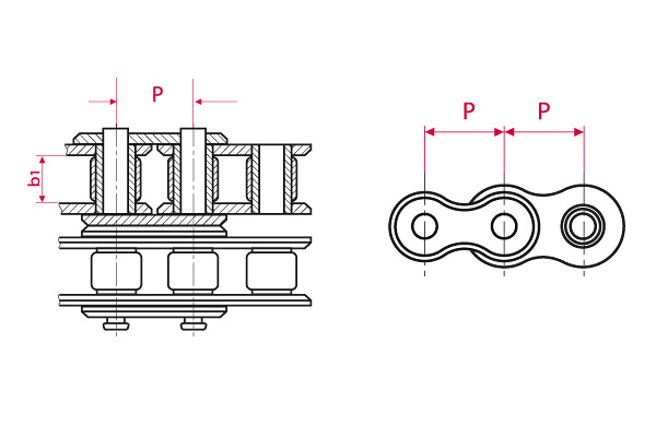
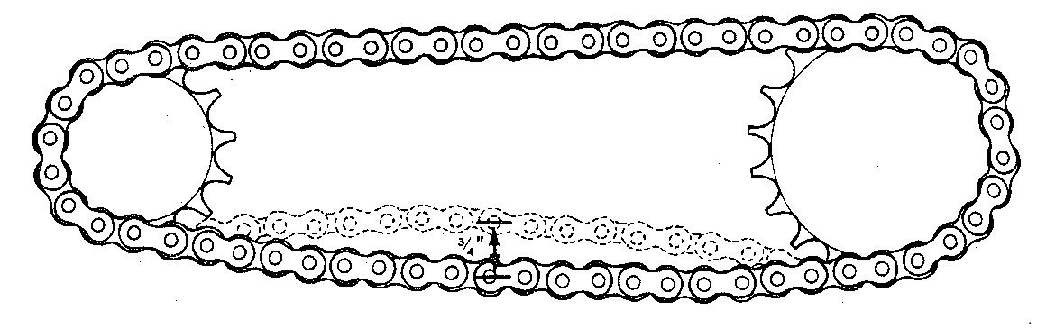
Glenn said we had to purchase a new primary chain, of which dimensions were: 62 links, duplex, 3/8 inches by 7/32 inches

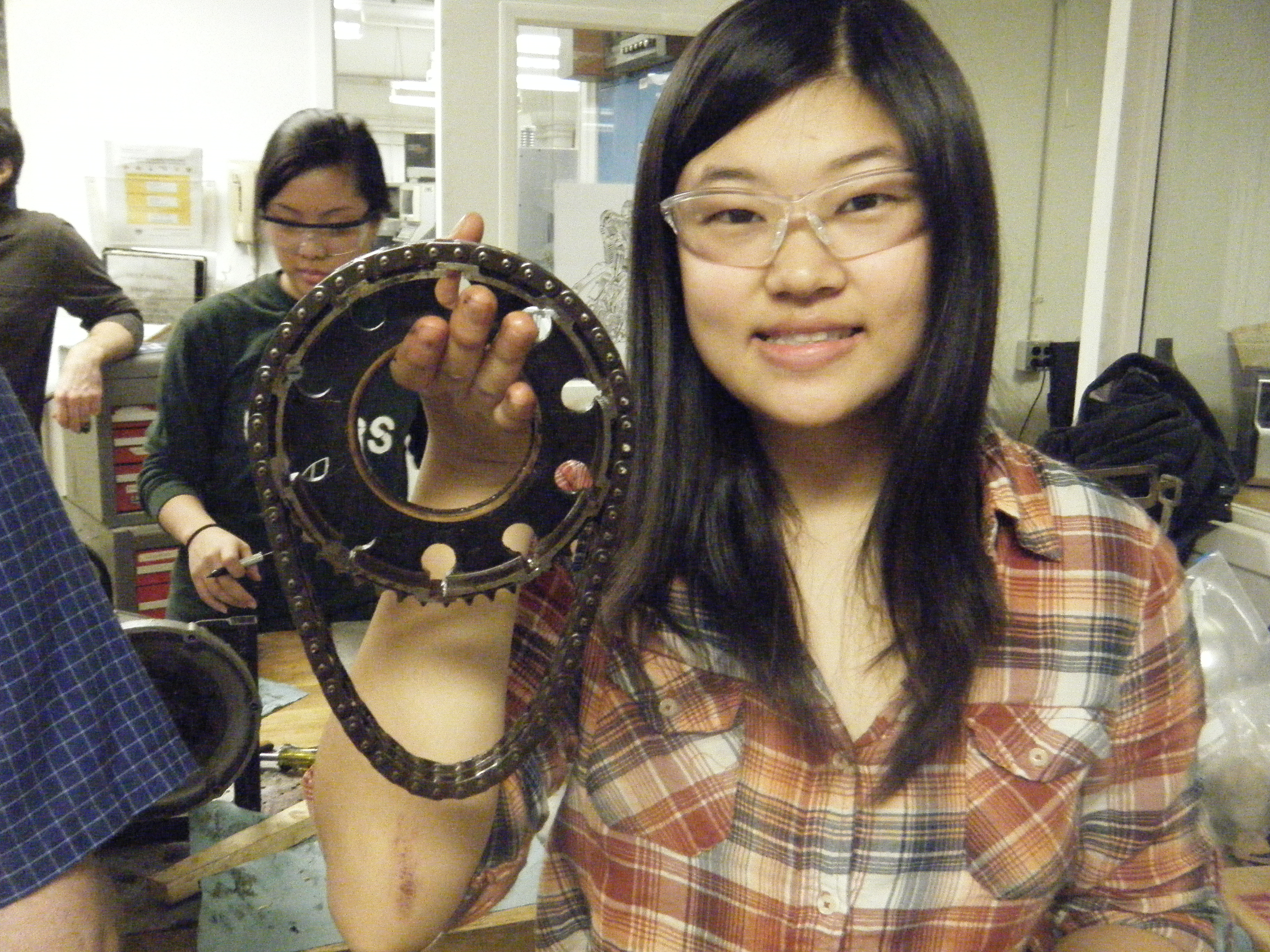
The primary chain connects the smaller engine sprocket with the larger clutch sprocket. Plates are contained within the “basket” of the clutch sprocket. As shown below, it is important not to have too loose of a primary chain. The duplex chain that the T20SR has provides extra support – a single chain may loosen from wearing down.
At the end of the day, WE SAW OUR CLUTCH! <3 🙂
Week 2 — 2/14
Preparation for disassembling the clutch and chain
For the first day we studied the function of the clutch. We found that the clutch transmits power from the engine to the transmission. The clutch is made up of a series of spring-loaded plates. When they are separated the transmission and power are not connected and the wheel of the motorcycle does not turn. When the plates are pressed together a connection is made between the power and the transmission. This is useful when the rider wishes to switch gears.
We also identified the location of the clutch, the different components of the clutch, and the different types of chains. The clutch is located on the left side of the bike, above and left of the kickstand. It is controlled by the clutch lever which is located on the left handle bar. These two components are connected by the clutch cable. The clutch is composed of two types of plates (friction and steel). Around these plates is the primary chain. A separate rear chain is larger than the primary chain and is located around the gears and the clutch..
Lastly, we consulted the Triumph Instruction manual to determine the best way to take apart the clutch.