What is the Top End?
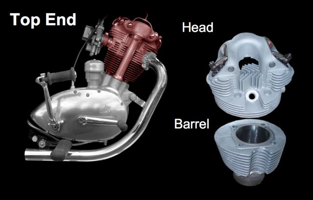
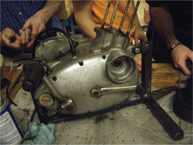
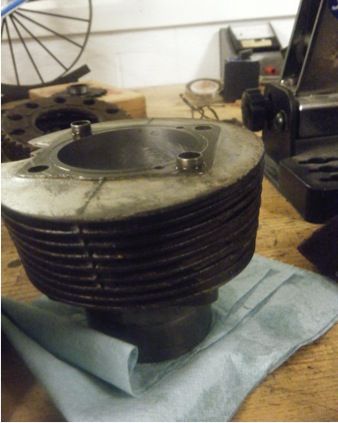
The Top End contains two main parts, the engine head and the barrel. These two components sit on top of the rest of the engine, hence the name “top end.” The following photograph shows the position of the Top End in relation to the rest of the engine as well as the division within the Top End between the head and the barrel.
Four Stroke Engine: The Otto Cycle
How we went about restoring the Top End
The Top End group got right to work, even before the groups were officially decided. On the very first day of class we took off the carburetor and the valve covers, then pulled the engine out. After that we removed the head and the barrel from the rest of the engine assembly.
We took apart the valve assembly in the head, carefully bagging and lbeling the parts. Many of the parts were dirty and rusty, so we cleaned the accumulated grease and debris off of them in the parts cleaner. We removed the park plug, the rocker arms, valves and vlave springs.
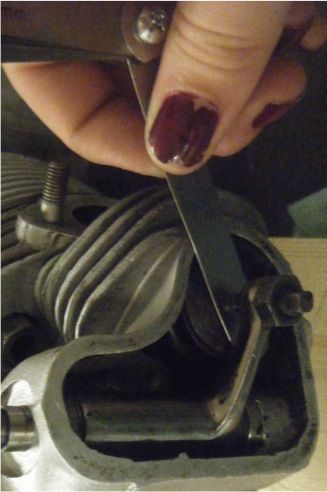
After disassembling the head, we sealed off the ports with masking tape, and then cleaned the head in the glass beader. We also lapped a mismatched joint in the exhaust port with Professor Littman and ground and cut the valve orifices for a perfect fit.
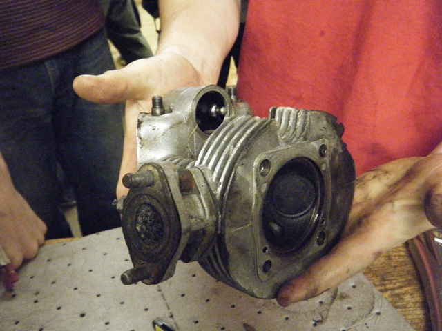
The Engine Head
Air and fuel flow in and out of the engine through the head. These fluids travel through passages called ports, and the flow through the ports is controlled by valves.
A mixture of fuel and air, combined in the carburetor, enters the combustion chamber through the intake port. The intake valve opens as the piston retracts on its “intake” stroke, and the lower pressure in the engine (because the volume is expanding) pulls the fuel-air mixture into the combustion chamber.
On the power stroke (after the fuel-air mixture has been compressed) the spark plug fires and the fuel explodes, consuming the oxygen in the air. The explosion increases the pressure above the piston in the combustion chamber, pushing it down the cylinder in the barrel.
This explosion creates a large amount of heat, which must be dispersed (or else the engine will expand too much and seize, or parts will gall and weld together). Our Tiger Cub is air-cooled, so the head and barrel are covered in fins to increase surface area and thus increase the rate of cooling. Most modern motorcycles have fluid-cooled engines, however. This requires a separate system to pump and store the fluid, so the Tiger Cub benefits from a simpler design in this respect.
After the explosion, the gaseous byproducts of combustion leave the combustion chamber through the exhaust port. When the power stroke is complete, the exhaust port opens. As the piston returns to the combustion chamber, it pushes the exhaust out of the cylinder.
Just to reiterate there are four strokes:
- Intake
- Compression
- Power
- Exhaust
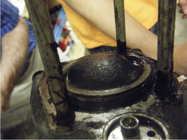
The barrel houses the piston in a lubricated shaft called the cylinder. Explosions in the combustion chamber in the head propel the piston down the cylinder. The engine’s momentum brings the piston back up the cylinder in time for the next explosion (according to the Otto Cycle).
Our Tiger Cub’s barrel is made from cast iron, because the cyllinder needs to be lubricated with oil and cast iron’s porous composition allows it to retain more oil. Inside the cylinder, there are a slight vertical grooves that enable the oil to flow up and down with the piston.
(On a side note, we learned that although cast iron is quite porous, it is also very brittle and if you bend it in a certain way it can break easily. This happened with one of our piston rings which was also made from cast iron)
Like the head, the barrel has numerous fins to dissipate the heat generated during combustion.
Over the course of millions of revolutions of the engine, the piston weas the front and back sides of the cylinder, making the cylinder oval insstead of circular. This becomes a serious problem preventing the engine from running smoothly, because the piston loses its seal against the sides of the cylinder, allowing the pressure from the explosion to leak past the piston instead of moving it.
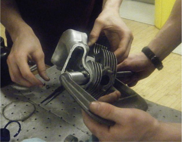
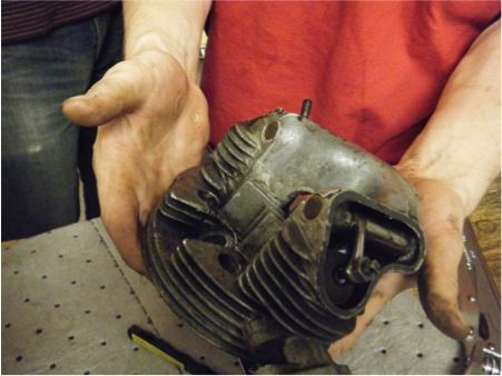
Removing the head:
Barrel Restoration information
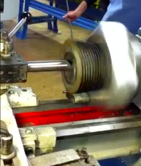
The most important task of the Top End restoration was to re-bore the cylinder. Glenn had built an aluminum jig that allowed us to put the barrel on the lathe, so we were able to bore and hone the cylinder on the lathe. First, after much measurement, we determined that the cylinder was actually quite close to cylindrical (in the best condition of all the previous Tiger Cubs), but would need to be bored from 30 thousandths-of-an-inch over its original specification to 40 thousandths over specs. Clearly, the cylinder had been restored before, and we were fortunate that the last job wasn’t entirely worn out. Despite its almost adequate condition, we re-bred the cylinder.
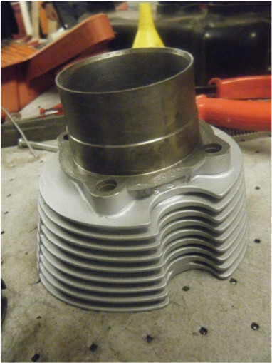
The barrel was dirty and corroded, so we cleaned it thoroughly in the parts cleaner. Then, we taped it up and glass-beaded it to get more grime off. Finally, we painted it silver with a high temperature paint to help protect it against future corrosion and to match the shiny engine head.
Boring the Cylinder
Bored and Painted Barrel
Valve Assembly
- The valves open when they are pushed down, and springs return them to their closed position.
- Levers called rocker arms push the valves down to open them.
The valves must be sealed closed when the combustion phase occurs, or else the explosion will travel out the ports.
- To have a good seal, the valves need to have a perfect connection with the seats where they rest.
- The valve and valve seats should have three matching faces of 30°, 45°, and 60°.
- This can be done by grinding the valves and cutting the seats.
Valve Components
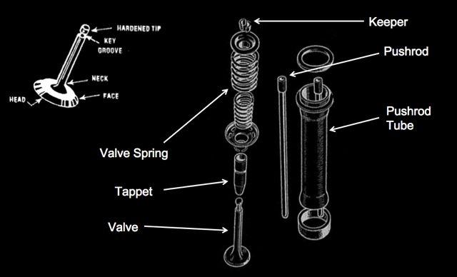
Diagram of Camshaft, Pushrods, Rocker Arms, and Valves

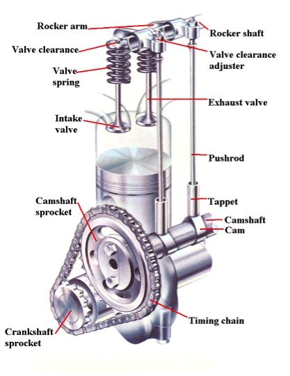
The Blue and Red lines represent the Standard Cam
Valve Spring Calculations
Restored Head and Barrel
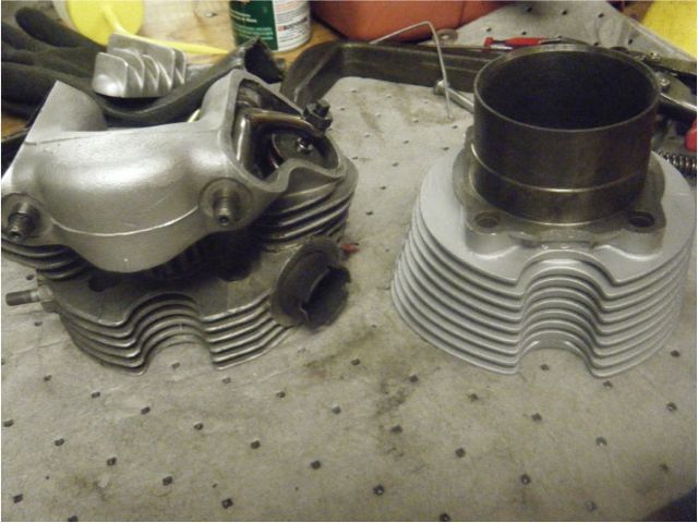
This is our final product: the engine head and barrel, cleaned, repainted, and in good working order. Not pictured are the impressive Princeton ’15 aluminum valve covers that PJ designed on ProEngineer and we produced on the CNC milling machine.