


NOW OUR DAILY JOURNAL
 We started by removing the handlebars. It was important to remove these first so that we could allow room for the other groups to begin their own disassembly. It may seem like removing the handlebars would be a relatively simple task, but they actually contained many complex components that had to be disassembled individually.
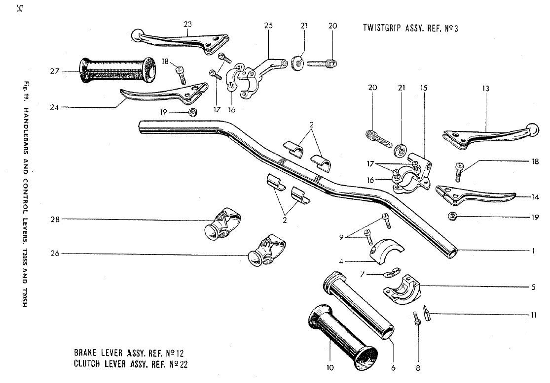
This is a diagram of the many components of the handlebars, each of which had to be individually taken apart. Note particularly the four pieces numbered item 2. These are called packing pieces and are fitted specifically to the handlebars, so we had to be sure not to lose them. On the handlebars is an engraved ribbing pattern that prevents the pieces from slipping, thereby preventing the handlebars from moving backward or forward while the machine is in motion. Our bike was also missing the left handlebar grip (no. 27). Luckily, we had the right handlebar grip, seeing that this piece is needed to rev up the engine. Another important piece is no. 24, the clutch lever, which the driver pulls to take in the clutch to shift gears. No. 14 is the brake lever, which controls the front brake. The complete list of parts is included below.
Taken from the Tiger Cub Replacement Parts Catalogue.

DAY TWO

We continued the disassembly of the frame, focusing on the big pieces, which will later have to be disassembled even further into the individual parts so that they can be sent to be powder-coated.
These are bolts taken out from the bottom rod pieces of the front fork. Notice that one bolt has three washers stacked on it, while the other has just one. Each bolt should be the same length and have only one washer. The previous owner, however, presumably did not have two boltsof the same length, and instead placed multiple washers on the longer bolt to keep it from going in too far and piercing through the other side of the frame. This causes extra wear on the frame and, stylistically, it is a fashion no-no. Somebody call the fashion police!
DAY THREE


Using the giant socket wrench. Note the extra-long handle, which gave us extra leverage and made the job of loosening the nut much easier.
DAY _____
In order to continue taking apart the forks, we had to hammer the especially jammed rod (pictured here) out. We used the metal rod with grooved screw end tool (see two pictures below this) created by Glenn, which screwed into the part of the frame pictured below. We hammered the metal rod instead of the frame so that we would not damage the frame by hammering it directly. In order to remove the piece jammed in place, we also placed a wedge in the slit in the frame (pictured here) to try and open up the part of the frame holding the rod in place.


February 23, 2012
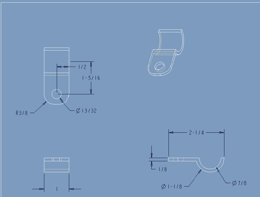
The seat mounts, which attach the seat to the frame, were poorly cut by someone else and welded on with sub-par craftsmanship. We need to grind off the old seat mounts and create new seat mounts that we can weld to the frame. We took some measurements from the current seat mount/frame configuration and Glen used CAD to draw up a 3D model of the seat mounts that we need to create. The diagram below shows one seat mount (the two are identical) from three different angles and includes the measurements for each part. After creating the diagram below, Glen created code for a program that will use a machine to cut out the seat mounts from a given block of metal.
We then went through all the parts of the frame and determined which ones need to go to the powder coaters. We had to pound out the bushels from the swing arm with a speically designed tool so that they do not get painted into place during powder coating. We have a new set of bushels, so we were able to throw the old ones out and we can put the new ones back in after the swing arm gets back from powder coating. We also had to remove a few last bolts from various parts of the frame, because we don’t want any removable pieces left in when we send the frame to the powder coaters. The pieces of frame that need to be powder coated are all set aside and ready to be sent out now.
We also designed a piece on CAD that will cover the opening of the fork piece so that the powder coating does not get into the forks. Glenn will make two of these pieces, most likely manually on the lathe, and screw them onto the top of the fork openings before we sent the frame to the poweder coaters.
an excitiing day

We made the fork caps on the lathe. Starting with a solid aluminium cylinder, we used a drill bit in the lathe to first hollow out a cylinder with the exact correct diameter in one end of the aluminum piece. Then we used a bit with a special end and put the machine on automatic in order to put threadsd into the piece. We repeated the same process on the other end and then cut the aluminium piece down the middle so that we had two identical caps. We put the caps on the forks and they fit!
Then we used the mill to take measurments for a gasket for the clutch-side cover. With the cover piece bolted down, we made a random place in the bottom left (0,0) and then moved around to each hole, recording the coordinates.