Part of the work of the electrical team included understanding the physics that allows the electrical system to function. Here we will give a description of the basic physics related to the electrical system and discuss the applications of those physical principles.
Physics of the Alternator
Magnetic Fields and Wires
In general, moving charged particles create magnetic fields. Likewise, we can conceptualize a wire as a “charge tube” that carries charged particles, and a current as the movement of those charged particles through the wire. If we assume these two statements to be true, we see that currents through wires produce magnetic fields.
If currents through wires indeed create magnetic fields, the next question one could ask is in what direction are these magnetic fields and what are their magnitudes.
Using a trick called “the right hand rule” (pictured below) we can determine the direction of a magnetic field produced by a current in a wire. If you point your thumb in the direction of an electrical current (note that this is the direction in which positive charges flow) and curl your fingers, your fingers will begin to form a concentric ring around the wire (your thumb) at the center. The direction of this concentric ring formed by your fingers represents the directions of the magnetic fields at the points along the ring.
Regarding the magnitudes of these magnetic fields, the field is the largest at the concentric rings closest to the wire and decreases as the ring’s distance from the wire increases.
The key idea of this section is that currents in wires produce magnetic fields and their direction is given by the right hand rule.
Flux
The next key idea to understand is the concept of flux. In relevance to the motorcycle’s electrical system, we can talk about flux in regard to any closed loop of wire.
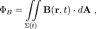
3 variables determine the magnetic flux that passes through the wire: The area of the loop of wire (A), the magnitude of the magnetic field that passes through the loop(B) , and the direction of the magnetic field that passes through the loop with respect to the normal line protruding from the loop(theta). When multiply these values B*A*cos(theta), the number we get is the flux of the loop.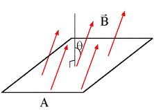
This description (B*A*cos(theta)) is a simplification of the definition of flux as the surface integral of the magnetic field. The advantage of the surface integral is that is allows possibilities such as a varying B field or a curved surface area. This equation is given by:
An appropriate question now to ask is what is the meaning this concept of flux that seemed to come out of nowhere? Flux is important, because a change in flux induces a voltage.
What does this mean exactly? A change in any of the 3 variables above (B, A, or theta) will induce a voltage in the wire- if we increase or decrease the magnetic field we create a voltage, if we shrink or expand the loop we create a voltage, or if we spin the loop, we create a voltage. More formally, this means that induced voltage is equal to the time derivative of magnetic flux. Even more formally though, this is Faraday’s law of induction, given by:
Magnetic Fields and Wires + Flux
With this mathematical understanding of flux, how can we conceptualize what is happening? Induced voltages caused by changes in flux can be explained by the statement “flux doesn’t want to be changed.” Any time we change the magnetic flux through a loop of wire, the reason why a voltage is induced in the wire is because “flux doesn’t want to be changed.” How this possible? This is a due to the magnetic field induced by a current in a wire. Note that in a closed loop of wire, if current flows through the loop, magnetic field lines inside the loop point either directly inward or directly outward. If we change the magnetic flux of a loop of wire, the loop will induce a voltage in the wire in order to produce a current in a loop in order to create a magnetic field to prevent flux from changing.
In other words, if we attempt to change flux through the loop, the loop will try to keep its flux fixed. For example, if we attempt to increase the loop’s flux, the loop will attempt to decrease it, and if we attempt to decrease the loop’s flux, the loop will attempt to increase it. How does the loop change its flux? By changing the value of B, the magnetic field passing through it. How does the loop change the values of B? By creating a current in the loop of wire that creates a magnetic field in the appropriate direction. How does the loop create the current? This is where the induced voltage comes into play, which we defined above as Faraday’s law.
So what?
Why is this relevant to our motorcycle? If we take a journey on down to the alternator, we will see that what we basically have is loops of wire and changing magnetic fields.
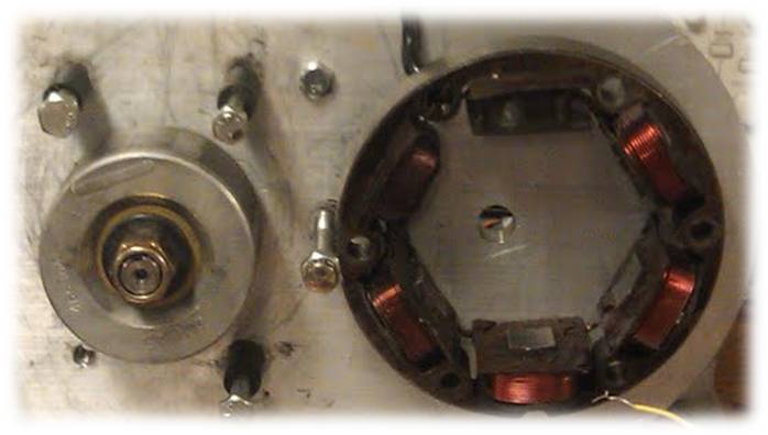
The alternator is composed of a rotor, which is a six pole permanent magnet, and 6 coils of wire (consider these wire coils to be a bunch of loops stacked on top of each other). The rotor is located inside the stator and its magnetic fields point through the center of the coils.
Awesome! So basically whenever our bike is running our alternator is creating a voltage! What is this voltage used for? All kinds of stuff- the headlights, tail lights, stop light, blinkers, horn, and speedometer all use this power. Most importantly though, this voltage helps to power the engine itself! We expand on this idea in the next section.
More applications!
The alternator on our motorcycle has 4 different voltage outputs. How is this possible? By using different numbers of windings in the coils of the stator, the alternator is able to produce voltages of 4 different magnitudes for a single stator velocity.
Awesome! So basically when ever our bike is running our alternator is creating a voltage! Why it is this voltage used for? All kinds of stuff- the headlights, tail lights, stop light, blinkers, horn, and speedometer all use this power. Most importantly this voltage helps to power the engine itself! We expand on this idea in the next section.
Energy Transfer System
How the high voltage wire keeps the bike running
In other sections of the website, we referred to the electrical system as an “energy transfer” system. Here, we will attempt to explain what this means and how the circuit formed by the wiring harness works to keep the motorcycle running.
Perhaps the best way to describe an energy transfer system is by comparing it to a battery ignition. With a battery ignition, a battery outputs a constant DC voltage and is charged by the AC alternator. With a energy transfer system, the AC voltage from the alternator powers the motorcycle directly.
So how does this all work? First, to clarify- there are 4 wires the lead out of the alternator: a ground, a low voltage, and medium voltage, and a high voltage. The low voltage and medium voltage wires are used to power the various lights on the bike and the high voltage wire keeps the bike running. In this discussion, we are only considering high voltage wire, because we are talking about the system that actually powers the bike.
So, an energy transfer system works basically by transferring energy between various elements of the wiring harness that we described in the “Key Components” section of the websites. At an given time, the points are usually closed. When the points are closed, energy is stored in the inductor in the alternator and current flows from the alternator to ground. Then, when we open the points, we get the exciting effects that make up the energy transfer system.
What exactly goes on here? First, when the points open, the magnetic field in the inductor collapses. This energy that was stored in the inductor (1/2*L*I^2) then goes directly to the capacitor (1/2*C*V^2) because a capacitor acts like a wire and an inductor (the coil) acts like a resistor when current starts to flow. Once the capacitor is charged though, it acts likes a resistor and the coil acts like a wire. As a result, the capacitor dumps its energy to the coil. The coli, which acts as a transformer, steps up this voltage up, and as a result, forms a high voltage spark across the spark plug (which then causes the explosion in the engine). By, this time the points should be closing. This whole process happens in an instant and occurs repeatedly for each explosion in the engine.
Timing is especially important to this process. First, it is important to time the spark such the explosion occurs during the proper stroke and precise moment of the engine cycle. It is likewise important to time the opening the points at the time at which the voltage produced by the alternator is at a peak. Unlike a battery powered electrical system, which supplies a constant voltage, an energy transfer system supplies a alternating current, or oscillating voltage level. To ensure the best spark, it is necessary to open the points at the time at which voltage is the greatest. This is one of the advantages of a battery powered electrical system- with a battery powered electrical system this aspect of timing is not important. Batteries to though have their draw backs- for example if you leave the lights of the motorcycle on and the battery dies, there is no hope of your bike starting on its own. With an energy transfer system, there is no battery, so this is never a problem. Today, most cars an motorcycles have battery powered electrical systems, but energy transfer systems are still found in small devices such as weed whackers and lawn mowers. In all, energy transfer systems are reliable, compact, have a rather dynamic name, and supply power to the bike with elegance.