General Rules Governing Circuits, and the Water Analogy
To fully comprehend how a circuit works, a few basic core concepts must be understood. Understanding these concepts is often aided by using the water analogy to compare them with the behavior of water in various circumstances.
Charge – A particle’s charge describes its behavior in circumstances involving electric and magnetic forces. As Thomas Edison discovered experimentally, there are two types of charges: positive and negative. Like charges repel each other, and opposites attract. For the water analogy, consider charges as water molecules.
Current – Moving charges create an electric current, in the same way that moving water molecules create a current of water, like a river.
Voltage – Voltage is the difference in electric potential at two locations, where electric potential is the buildup of charge. Think of this as the water pressure in a pipe system: water at a higher pressure (higher electric potential) wants to move toward the lower pressure (lower electric potential) water until equilibrium is reached, and the difference in pressure between the high and low pressure points is akin to the electric potential difference, the voltage, in a circuit. The term voltage, then, is always a comparison of two values. Typically in electrical appliances labeled with a particular voltage value, it means the voltage of the appliance relative to ground (the earth’s potential, often considered to be at 0).
Basic Circuit Laws: Circuit components are generally considered to be “in series” (one after the other) or “in parallel” (branching from one source). For example, in our circuit diagram, the wires leaving the alternator (our power source) are in parallel with each other. When wires are in parallel, the parallel components are at the same voltage, the sum of the current through each component equals the current through the source where the parallel components branched from. When wires are in series, the current throughout each component in the series is the same, and the sum of the voltage across each component of the series equals the voltage across the ends of the total series.
Electromagnetic Induction
Magnetic Flux
Magnetic flux is the amount of a magnetic field passing through an area. It’s represented mathematically by the following equation:
![]()
From this equation, we can see that magnetic flux changes with changing magnitude or direction of magnetic field, or changing area or direction of the area through which it passes.
Faraday’s Law
By Faraday’s Law, a change in flux over time through a loop of wire induces a current.

For a coil of N turns, the induced voltages add as batteries in series would.
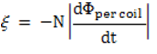
In our machine, as the rotor rotates the magnetic field passing through the area of the stator coils changes. This causes a change in magnetic flux and thus induces voltage in the stator windings. As the change in flux is both increasing and decreasing at different times, the direction of the induced current alternates. Thus, AC voltage is induced in the coils.
Transformers
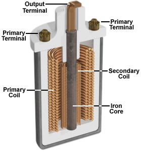
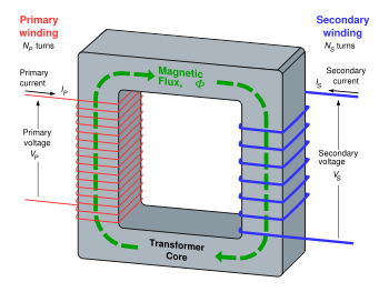
A transformer consists of two coils of wire denoted the primary coil and secondary coil. Both coils are wrapped around a common core of some ferromagnetic material (typically iron).
The primary coil is driven by an oscillating voltage (so current flows in both directions in a sinusoidal pattern over time)
By Faraday’s Law, the alternating current through the coil induces a magnetic field inside of the coil and thus magnetizes the ferromagnetic core. As the core is magnetized, it passes through the secondary coil and creates a changing magnetic flux. Thus, an oscillating voltage is induced in the secondary coil.
According to Faraday’s Law, the induced voltage in the secondary coil is proportional to the number of windings in the secondary coil. The magnetic field induced in the primary coil is inversely proportional to the number of windings in the primary coil.
![]()
![]()
Thus, the ratio of the number of windings in each coil determines ratio of the voltages in each coil.
![]()
This device essentially transforms the voltage. A step-up transformer has fewer windings in the primary coil so the voltage increases in the secondary coil. A step-down transformer has more windings in the primary coil so the voltage decreases in the secondary coil. Because energy is conserved, and increase in voltage leads to a proportional decrease in current (and vice versa).
(image1) http://www.electricityforum.com/images/electrical-transformer-design.jpg
(image2) http://www.magnet.fsu.edu/education/tutorials/java/ignitioncoil/index.html