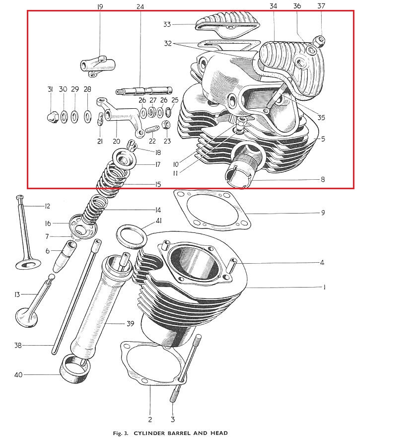
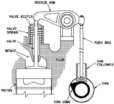
Cam and Valve Diagram
 The cam assembly consists of –
- the cam
- cam followers
- push-rods
- rocker arms
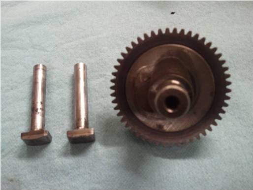
We have the R-type cam, which is the higher performance cam.
R-type Cam and Followers
Our Engine
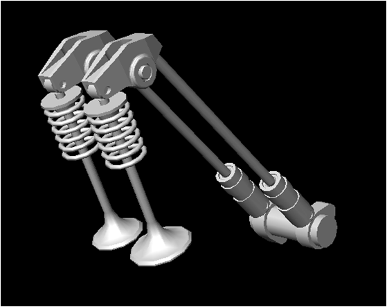
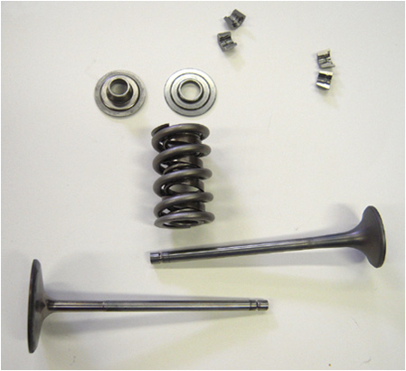
In our engine, we have two cam lobes and two push-rods controlling two valves.
There are two oppositely-coiled helical springs which bring the rocker arm and valves back to their original position after each half-cycle, and help in keeping them in position.
Valve Seats
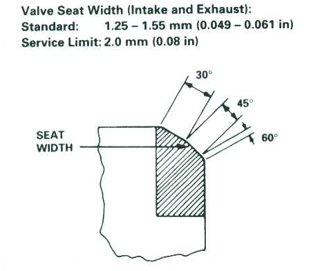
The valve seats had to be recut, and we decided to do a three angle valve seat.
The purpose of the seat is to form a surface for the valve to seal against during the compression and combustion stroke, so that the cylinder does not lose compression. If it does not seal, expanding gases will escape around the valves, lowering our efficiency and probably causing damage in the head.
A three angle valve seat is a popular method for higher performance engines. The idea here is to create a small, uniform ring at the correct angle to form a seal against the valve.
- If the area of the seal is too large, the valve will not form a good seal.
- If it is too small, there will be a good seal but the metal will overheat, warping and damaging it and the valves.
- The happy medium is made using three cutting tools, each with a different angle.
The process involved the following three cuts-
- The first angle we cut is around 30 degrees. This is the base cut, where most of the metal was removed.
- Once we had that angle well under the valve, we cut the 46 degree angle, the mating surface.
- We intentionally made this surface larger than necessary, so we could bring down to exact tolerances with the 60 degree cutting tool.
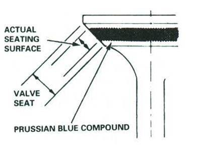
Once the correct seat was established, we lapped the surfaces to match exactly with the valves using a grinding compound, which was placed on the mating surface of the valve.
The valve was inserted into the correct position and spun, first by hand with coarser grit and then with a drill with fine grit.
Detail of Mating Surface on Valve
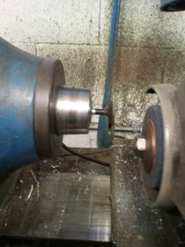
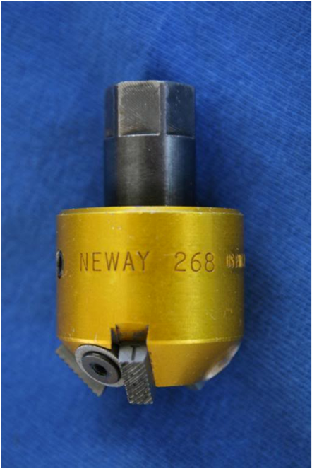
Cutting Tools
This tool is used to cut the valves seats at a specific angle determined by the position of the three cutters. Each tool has one predetermined angle, therefore we used three different tools to cut our high performance three angle valve seats.
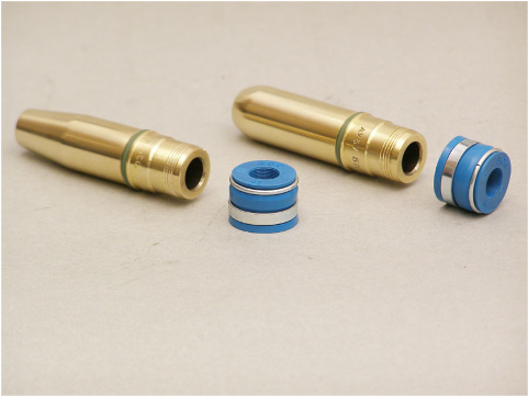
The Valve Guides serve a dual purpose –
- Along with the valve springs, the valve guides serve to positively locate the valves so that they can make proper contact with the valve seats.
- They serve also to conduct heat from the combustion process away from the valves and into the body of the cylinder head so it may be taken up by the cooling system.
Pro-Engineering Technical Drawing of Valve Guide
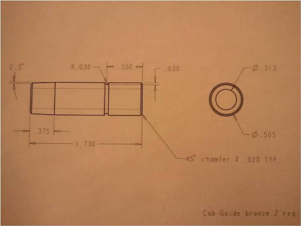
We decided to make new guides with Glenn’s suggestion.
We used some bronze bar stock that was in the shop, and drew up the dimensions of the old guides on Pro-Engineering, but enlarging them so we could drill a new hole for them to seat in, rather than hoping they would fit nicely into the old spot, which was probably worn.
They are also longer than the old ones, and have closer tolerances, which means the valves will move more precisely.
We made the guides on the lathe, first making one end square.
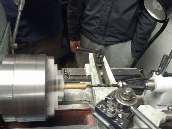
The next step was to drill the inside channel for the valves, then bring the outside down to the correct diameter. The angle cut was next and we added chamfers on both ends.
The final step was cutting the groove for a ring that keeps the guides at the correct depth in the head.