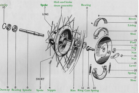
Front Wheel Diagram
Rear Wheel Diagram
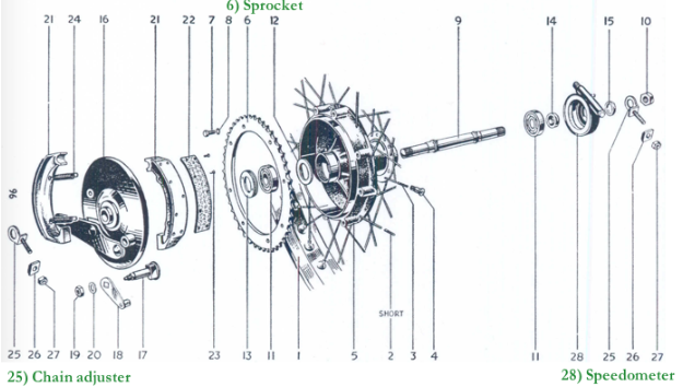
The parts of the rear wheel and front wheel are relatively similar apart from the 6) sprocket, 25) chain adjuster and 28) speedometer. The sprocket is the gear on the rear wheel that holds the end of the chain. Teeth connected with drive chain which is connected to the engine. The number of teeth on the sprocket affects acceleration, revolutions per minute (related to fuel economy), and maximum speed. (These are determined by the gear ratio of teeth between front and back sprockets.) In summary the most important parts of wheel are: The hub- within the hub are the axle and ball bearings-the spokes, and the rim.
Evolution and steps taken
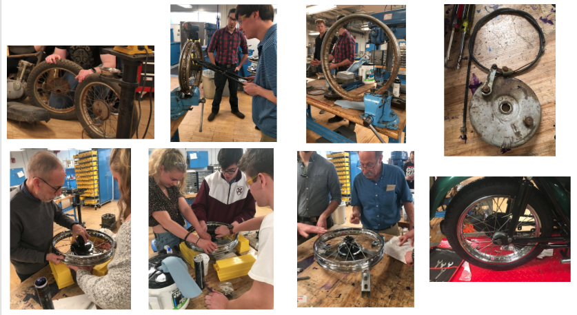
Steps to disassemble and reassemble the wheel:
- We inherited the wheels from the original motorcycle, and we needed to take them apart. We, therefore, started with the question: What part do we need to keep in order to reassemble the wheel? After consulting with Professor Littman and Al, we determined that the two hubs and the associated hardware were the main parts that needed to be retained. We could remove the old tire, rim, and spokes, because we had ordered new parts to replace the originals.
- On the first wheel that we approached, we attempted to place a tire removal tool between the rim and the tire, with the assistant of a lubricant. A significant amount of force was required to take the tire off. After finally removing the tire, we cut the spokes off. In light of the significant challenges encountered with the first wheel, we decided to use a saw to cut the tire off of the second wheel, and the saw penetrated the rim. Retrospectively, it would have been a good idea to keep the parts instead of throwing them out as a reference point for measurements later in the process.
- At this point, we just had the hub, with screws in it, an axel, and the hardware that held this fixture together. We spent a few days cleaning the hubs with metal brushes and sandblasting the parts. We then sent the two hubs off to be powder coated. At various points, there were multiple hubs in the mix: some from previous motorcycles, some from the 1963-2 Tiger Cub.
- While the hubs were being processed, we cleaned up other parts including: the screws, the axles, and other hardware.
- When we got the hubs back, we began to put the spokes on the wheel. This was one of the more challenging parts of the assembly process. There are different spokes for the bottom part of the hub (this circle has a larger radius, meaning that the spokes are closer to the rims) and the top part of the hub (this circle has a smaller radius meaning that the spokes are further from the rim). For the top part of the hub, there are inner and outer spokes of different lengths, because some enter in the gaps on the hubs from different orientations. The spokes do not go out radially in a line from the center of the wheel to the rim; rather, they sit in a vector at an angle from the vector in order to distribute force and allow for compression to take place. It took a number of tries to properly spoke the wheels.
- Bill Becker helped us with lacing the wheel, providing insightful advice on how to get the correct tension on the spokes and offset from the rim to the hub.
- After the spokes were properly attached to the rim, we needed to adjust for the tension and displacement. In order to accomplish this feat, we trued the wheel. We learned the art of “truing” the wheel in which we learned how to loosen and tighten the spokes to reduce the “offset”(wobbling). This entails putting the wheel on a special stand that allows us to center the wheel. There are two categories of displacement about which we were concerned: vertical and horizontal displacement. We used a special spoke wrench to make proper adjustments.
- To mitigate horizontal displacement, we adjusted the left and right spokes. If the wheel was offset to the left, we tightened the right side and loosened the left side to pull the wheel to the right. On the other hand, if the wheel was offset to the right, we tightened the left side and loosened the right side to pull the wheel to the left.
- To mitigate vertical displacement, which was manifested in the form of a slight dip of the wheel as it spun, we adjusted spokes on different vertical slides of the wheel with equal turns.
- LISTENED TO FREQ OF SPOKES
- PERMISSIBLE ERROR 1/16 INCH
- We spent many lessons trying to reduce the effects of wobbling which was a tedious challenge. Once we finally got the offset of the horizontal and vertical displacement correct, we repeated the whole process on the rear wheel.
- After truing the wheel, we affixed the axel.
- Lastly, using a special stand, we attached the tires to the rims.
Physics of the wheel
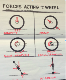
- The top half of the spokes are in tension when the wheel is moving. To avoid warping the metal, the bottom spokes will become less tense (in other words, compress) when the top spokes are tense.
- In order for the wheel to rotate, torque must be applied–which is a force that causes an object to move around an axis
- Geometry of the wheel –almost every wheel has clusters of four spokes, even though nipples are evenly distributed around the rim. Most wheels have 36 spokes, but for the British, there are 40 spokes because of differential forces between the rim and the hub when accelerating stopping.
Calculations
Torque calculation
3000rpm= fly wheel speed
420rpm= rear wheel speed
100 foot pounds= torque required to move rear wheel
420/3000= x/100
x= 14 foot pounds (to move flywheel/ get flywheel to slip)
(Torque is the twisting force produced by the engine which gets split up between the wheels; Multiple sets of plates in a clutch means multiple torques at which the clutch will slip)
What if our wheel had single spoke – what would the diameter need to be?
150 lbs= weight of bike
150 lbs= weight of rider (child)
300 lbs= total downward force; 150 lbs on each wheel
75,000psi=breaking point of steel
Breaking point=force/diameter
=75,000=150/A=.002 inches minimum diameter. This can be altered when supplementing with safety mechanisms, ext.
Young’s Modulus
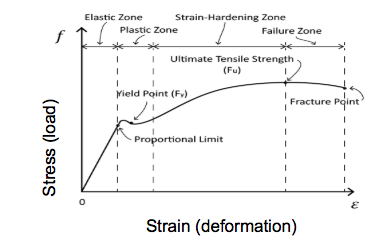 Young’s modulus is useful in determining materials properties. There is a relationship between stress and strain: At a certain point, the material will break (this point occurs after the working strength limit is reached.). Thus, it is important that each of the materials, particularly the spokes, on the wheels have been carefully chosen. Somoene can bend metal, plastic or another material up to a certain point before it becomes permanently bent.
SPECIAL THANKS TO:
- Professor Littman
- Al
- Glenn
- Jon
- Bill Becker
- All others in the class who lent hands with the wheels when we needed help!