Overall: What We Did
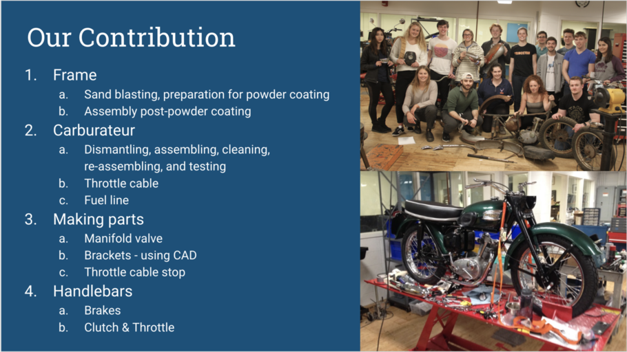
Our tasks over the semester were the following:
-
First, we worked on the frame. Our job was to assess it for weak points or cracks. We did this by using the sand blaster, which will be discussed more thoroughly later. We then sent the parts out for powder coating and chroming, and after we got them back, we worked to (re)assemble the whole frame.
-
Second, while waiting to receive the parts back from the powder coated, we worked on the carburetor. Our job was to assemble a carburetor out of the parts we had in the shop. We had to disassemble multiple Amal carburetors, clean the parts, reassemble one, and test it.
-
Third, throughout the process we also had to fashion parts of our own. For example, we needed a manifold to attach the carburetor to the engine, so working with Glenn, we were able to manufacture one. We also had to fashion a bracket for the seat from scratch using CAD. Lastly we made a piece for the throttle cable.
-
Fourth, our last project was to assemble the handle bars, including the break and clutch levers as well as the throttle.
The Frame: In Depth
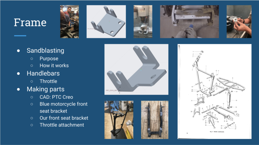
SANDBLASTING: Starting with the frame, our first job was to prepare it for powder coating. Thus, we had to assess the frame for cracks, using the sandblaster. The sand blaster uses compressed air that blows sand (or other abrasive materials) through a pointing tool to remove the top surface of material. We aimed it at each joint, and we ended up finding no issues on any of the parts.
HANDLEBARS: Then, later in the restoration process, after we had assembled the frame, we worked on the handle bars. Taking the parts we had from the chromer (the handle -bar- itself and the two levers as well as the brackets for each lever), we began to put them together. We also noticed that the threads for the levers and their brackets were unique for a Triumph motorcycle in that they were 10-32, so we went to stock room to pick up some 10-32 bolts.
MAKING PARTS: There were a few times during our restoration when we did not have all of the parts we needed, and it was either easier or more time effective to make them ourselves. The first time this happened was when we were changing the seat of the blue motorcycle. The old seat had a bracket soldered on to it, and also had attachment holes in a different configuration than the new seat, so we had to design a new bracket. In order to do this, we first used calipers to make measurements to inform our design. We then used PTC Creo to CAD the bracket we designed. We used a similar process to design a front seat bracket for our motorcycle. The other part that we had to make was the throttle attachment piece. We made measurements and created a sketch of the part. Glenn then helped us to use the lathe to manufacture this part. We then used a hack saw to cut a slit in the piece so that it could slide over the throttle wire.
The Carburetor: In Depth
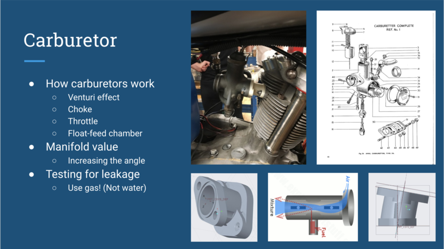
HOW CARBURETOR WORKS: Basically, the function of a carburetor is create the fuel-air mixture that will go to the engine for combustion. Central to how a carburetor works is Bernoulli’s Principle and the venturi effect. As the air flowing through the carburetor reaches the kinked part of the tube, the air speeds up and the pressure is lowered. The pressure differential that is created causes the fuel to be “sucked” up and vaporized. The carburetor choke, located above the venturi, regulates how much air can flow into the carburetor. This, in turn, can regulate the air-fuel mixture that is sent to the engine. The throttle, located below the venturi, sets how quickly the fuel-air mixture can flow to the engine. Inside a carburetor, there is a float-feed chamber, in which a small piece floats in fuel. As fuel is sent to the engine, the fuel level and float drop, and eventually, the float opens a passage through which the fuel can flow to refill the float-feed chamber.
MANIFOLD: the purpose of the manifold is to connect the carburateur to the engine. Its job is to let air and fuel into the cylinder for ignition. In the case of our motorcycle, we used a carburateur that was not meant for our bike, so we had to design a new manifold in the correct configuration. The main contribution that we made to the design of the manifold was, after seeing the white trial version shown above, telling Glenn that the angle should be increased from ten to twenty degrees. This provided for greater clearance between the top of the carburetor and the bottom of the fuel tank. It worked perfectly. Thank you Glenn.
TESTING THE CARBURATEUR: To assemble the carburetor, we first had to disassemble multiple different carburateurs to collect all of the parts we needed. Then, we cleaned these parts and assembled them into the one that we were going to use. Next, we had to test it for leaks. We originally were going to use gasoline to test but then we were told that we could just use water. We filled it with water, and our carburetor did not leak! Thus, we were done with our assembly. When we arrived at class the next day, we found that our carburetor was disgusting. Apparently, we had not drained it out enough, and the water had some sort of precipitate in it, so a strange white substance was left in the carburetor. When we tried to clean it off, we scratched off the top layer of aluminum for the carburetor, and it oxidized with the air, turning white. This led us to believe that we had not fully cleaned our carburetor, so we spent the class with carburetor cleaner attempting to clean it out completely, until we realized that we already had. Finally, we reassembled it again, tested it on the red motorcycle, and it worked! The moral of the story is that you should use the material meant to be in the part to test it. DON’T USE WATER.
Explored Calculations:
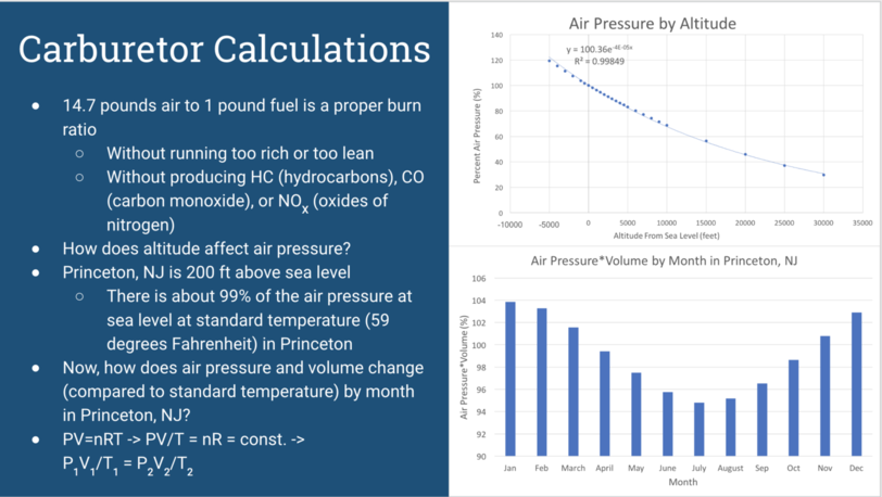
FUEL-AIR MIXTURE: As referred to in the previous slide, there is a proper fuel-air burn ratio. Based on the handout Professor Littman gave us, that proper ratio is about 14.7 pounds of air to one pound of fuel. With the proper fuel-air ratio, ideally engine would run smoothly, without excess heat, and without producing excess emissions.
ENVIRONMENTAL IMPACT: As we learned in our reading concerning carburation, hydrocarbons are raw unburned fuel, and they can pollute the environment. They are emitted in large quantities when the engine is running too rich or when there is engine misfire, which can be caused by excess heat in the engine. This excess heat could be caused by running the engine too lean. Carbon monoxide is essentially partially burned fuel and can also be a harmful pollutant if emitted in large quantities. If the engine is run too rich, there will not be enough oxygen during combustion, and carbon monoxide, rather than carbon dioxide, will be formed as a product of combustion. High cylinder temperature and pressure can lead oxygen to react with nitrogen, forming oxides of nitrogen, a third pollutant. These cylinder conditions can be a result of running the engine too lean.
CALCULATIONS: As can be clearly seen from this information, the balance of fuel-air mixture is sent to the engine is very important for both environmental reasons and for engine life. Thus, for our calculations, we decided to see how certain variables might affect air pressure, since changing air pressure would change the amount of air molecules being sent to the engine within each volume of air.
ALTITUDE: First, we explored a more straightforward question: how does altitude affect air pressure? Online we found data on the air pressure at different altitudes above and below sea level. We decided to convert those air pressures into percentages of the air pressure at sea level. This would make the data more legible to someone who did not know the scale of kPa, for example. Since Princeton, NJ is located at an altitude of about 200 feet above sea level, the air pressure is about 99% of what it is at sea level (at standard temperature, or 59 degrees Fahrenheit). This means that if you had your carburetor set properly at sea, you may want to ever so slightly lean it out in order to get a proper fuel-air ratio in Princeton.
TEMPERATURE: Next, we wanted to explore how air pressure changes by month in Princeton, NJ. To do this, we first found the average monthly temperatures in Princeton online. Then, we used the Ideal gas law, PV = nRT, to figure how out these temperatures would affect the pressure and volume of air. We solved the ideal gas law as can be seen on the slide to find that P1V1/T1 = P2V2/T2. We then solved for the pressure times volume of air in princeton, assuming that air is an ideal gas, during each month and found the percentage of princeton’s pressure times volume of pressure times volume for standard temperature. This graph shows the results of our findings. The main takeaway from this graph is that if you have your carburetor properly set in a hot month, you may need to adjust its settings during a cooler month.
Our Sources: