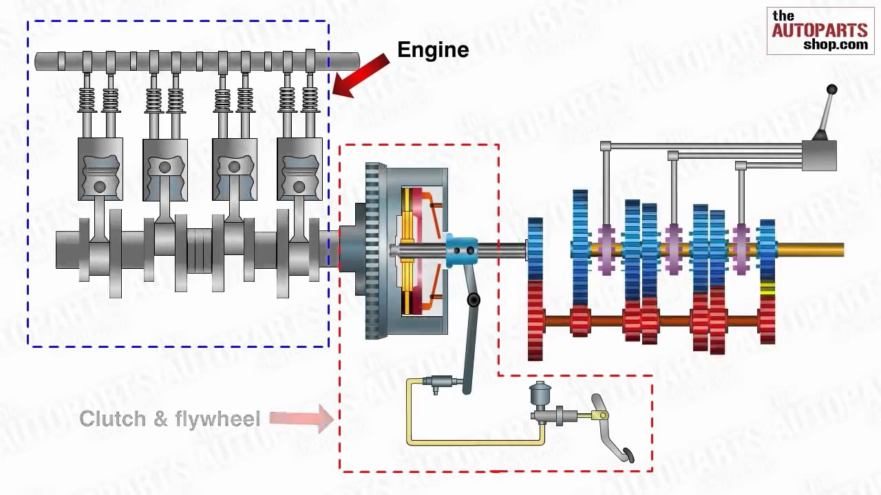
A typical clutch diagram in an engine. It transmits power from the crankshaft to the transmission.
A clutch is a key component in any internal combustion engine that supports gear-shifting. The clutch acts as a buffer between the power created by the engine and the power transmitted to the transmission, and the rear wheel. It does this by using frictioned plates that are compressed together, which can be pushed apart. When the plates – called clutch plates – are pushed together (usually by a spring inside the clutch), the power from the engine is transmitted to the transmission; when it’s pushed apart (by “releasing the clutch”) the engine can keep spinning without powering the transmission. This is important because when you’re shifting gears, you don’t want your powered shaft (read below!) to keep turning at a high velocity, or else a gear’s tooth might chip or crack when it is shifted into place.

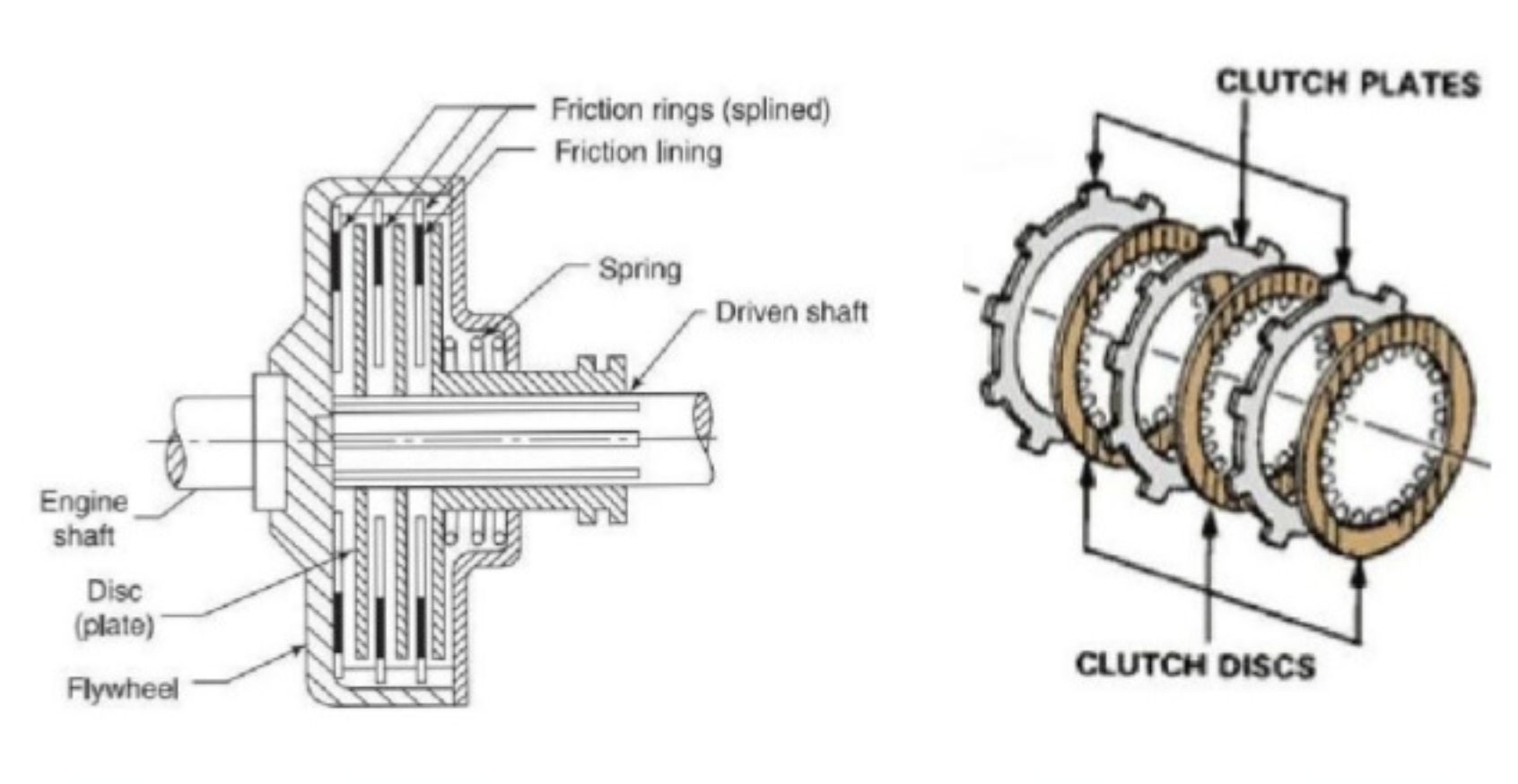
As you can see in this image, the clutch is comprised of several clutch plates that turn against each other. Some have teeth that connect to the “clutch basket,” which all the plates sit in, and some have teeth which lock into the driven shaft. The clutch basket is powered by the crankshaft sprocket, and the driven shaft goes straight to the transmission: see our diagram.
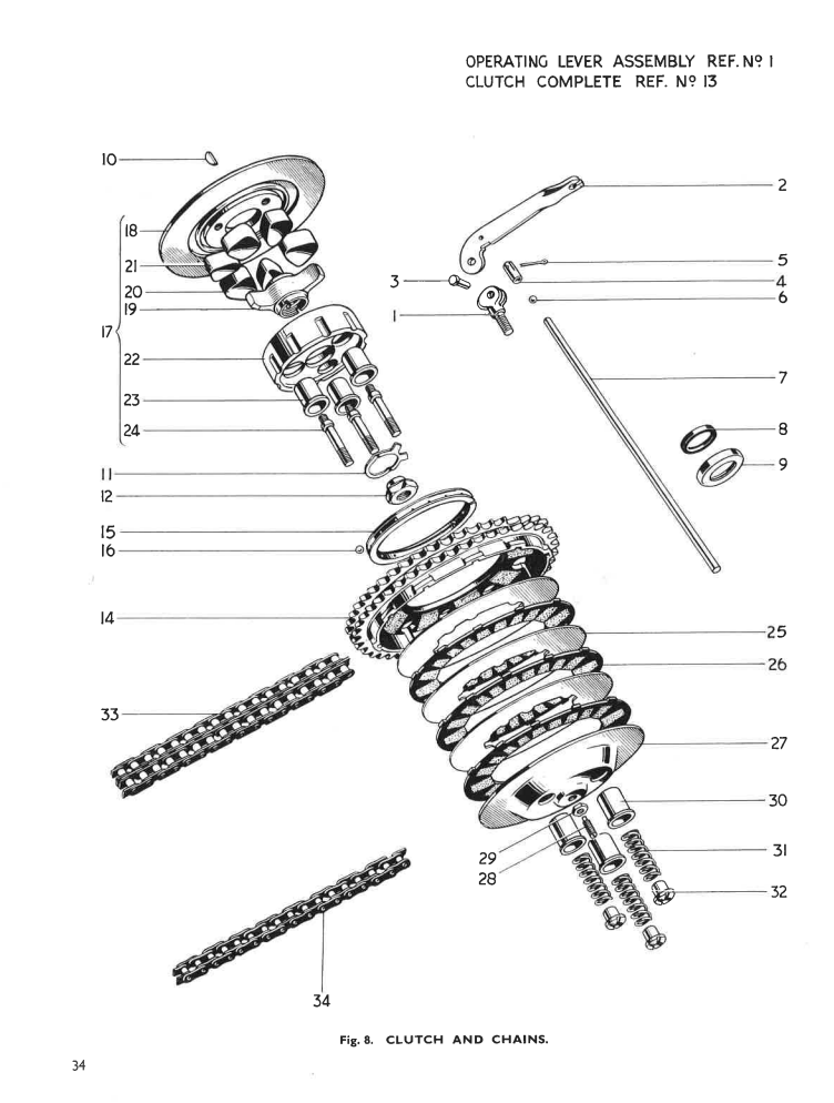
In this diagram, you can easily see the sets of black-colored clutch plates (item #26), with teeth that extend into the clutch basket (item #14), interlocking with the metal plates (#25) which connect to the driven shaft.
Another thing that the clutch is used for is when you’re speeding a bike up from neutral when starting it. As we learned in class, you can’t start an engine in gear or else the whole bike will drive away. Instead, you put the bike into the neutral gear, where no power is transmitted from the engine to the rear wheel, so that the engine’s crankshaft can start turning without the bike rolling away. When putting the bike into gear from this, you can’t simply shift from neutral to first. If you did, one shaft would be rotating at several thousand RPM (the typical speed of an engine’s crankshaft) and the other would be sitting still; when you tried to connect them something would very likely break (such as the engine stalling or a gear chipping). Instead, we pull out the clutch while the engine is still in neutral, then put the bike into gear (with the clutch still held). This way, the bike is in gear but there is still no power from the engine to the clutch. We can then slowly let the clutch back in by releasing the clutch handle, which slowly accelerates the bike because the force is now transmitted by cork friction pads, which work in both static and kinetic friction, rather than metal gears.
Our Clutch
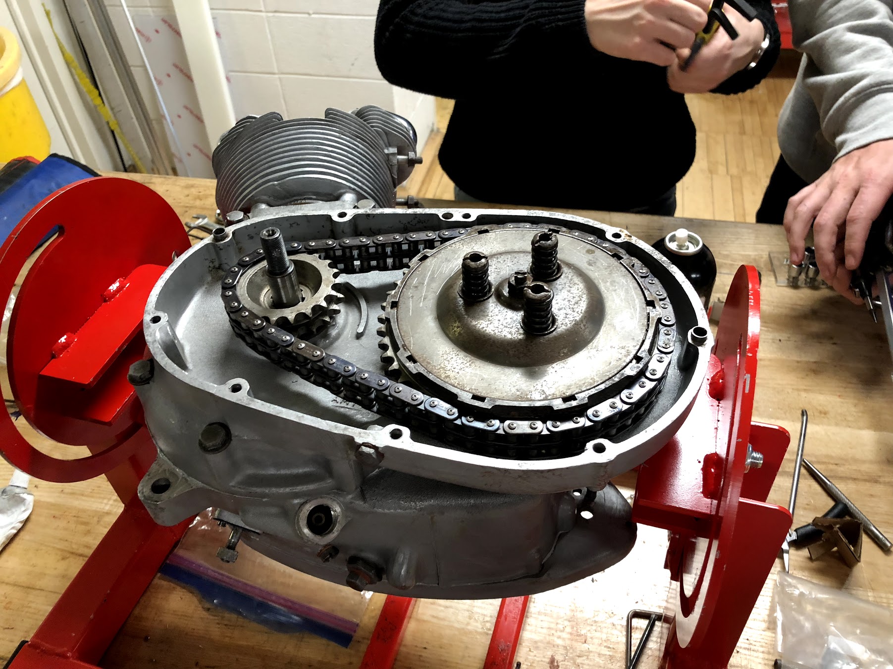
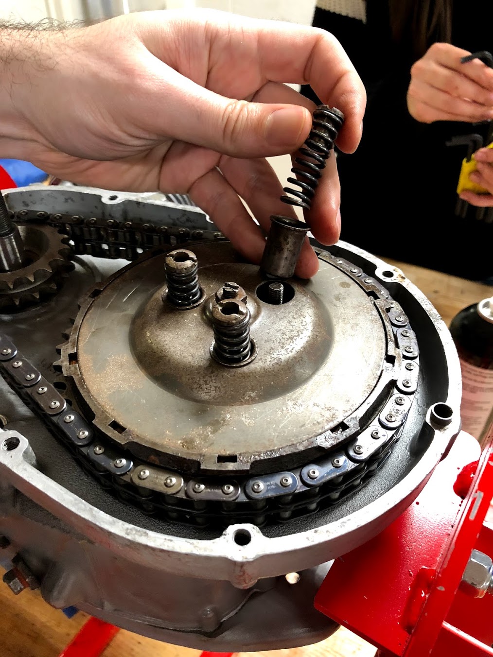
For our Clutch, we had to disassemble the clutch basket, thoroughly clean the metal interlocking clutch plates, and replace the worn-out cork plates with new ones. Before re-inserting the restored clutch, we made sure that all the inner materials were well-soaked in clutch fluid, which helps increase the static friction between clutch plates. We also had to make sure that the clutch springs were tight enough, because loose clutch springs can make the engine impossible to start: if the clutch plates simply slip past each other when the driver kicks the kickstarter, then the crankshaft won’t turn.


Why cork?
One last question we had was why our clutch plates used cork. In our daily lives, we almost never see cork outside of wine bottles, yet here it was in this random engine part. Upon closer inspection, cork turns out to be an excellent material for this purpose because it has a high coefficient of friction, which determines how much force it can transmit when pushed or slid against something. Formerly, asbestos was used in clutch plates because they had this same property (and were in fact even better at it!) but thankfully the harmful effects of asbestos lead to its replacement. Our clutch basket is intriguing in its use of cork because it existed some years after asbestos was replaced, but before the next major breakthrough in clutch plate material was developed: kevlar. In the modern day, kevlar is frequently used as a clutch plate material because it has an even higher coefficient of static friction, and it lasts longer than cork.
Why transmission?
This is a diagram of our motorcycle’s transmission:

How a transmission works
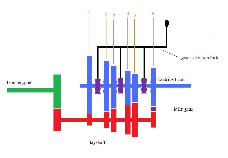
The green shaft transmits the power from the engine, and transfers it through a gear to the red shaft, the layshaft (also called a “countershaft” when it spins in the opposite direction from the drive shaft). The layshaft then transfers the power to the blue shaft, the main shaft, through one of several possible gear combinations, each of which has a different ratio between the number of teeth in the gears. The driver can change which combination is engaged using the selection fork, which slides the gears in and out of position.
Our Transmission
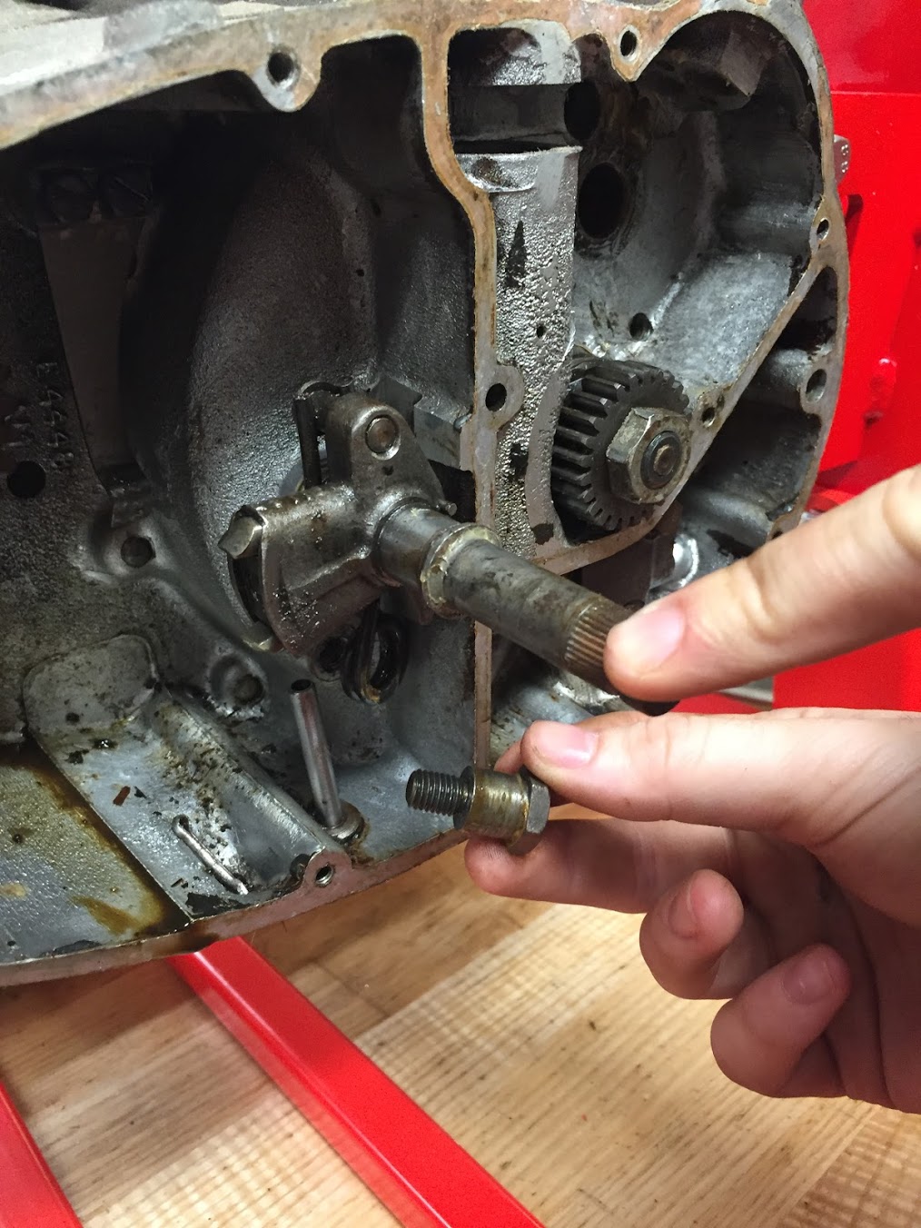
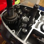
Our task was to take the transmission apart, clean it, inspect it for damage, and put it back together. When we examined it at first, it was not very clean, as you can see in these pictures:
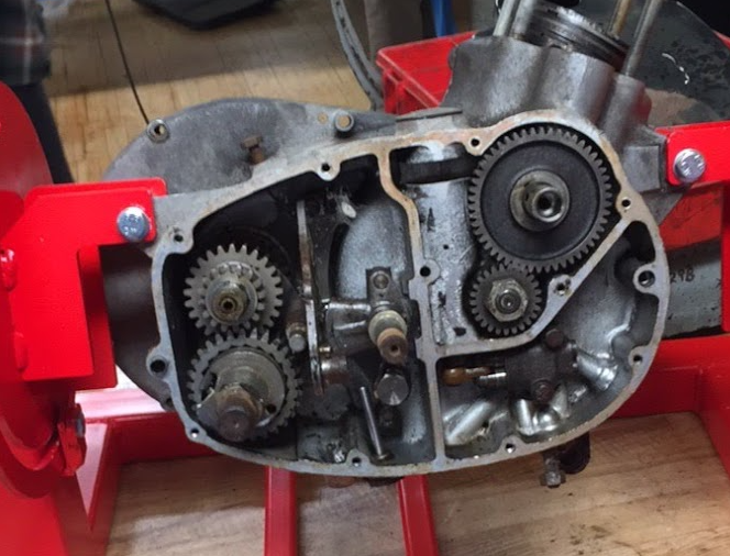
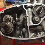
However, when we took it apart and cleaned it, we saw that it was in pretty good shape. None of the teeth on the gears were cracked, so we didn’t have to repair or replace them. There were a few parts missing, so we had to make or replace them. But overall, our transmission was in pretty good shape. Our cleaned and rebuilt transmission looked pretty good:
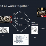
We created this flowchart to demonstrate how the gear ratios work together. On the far left you can see the engine, and its sprocket below it. That sprocket has 19 teeth, and the sprocket in the clutch basket has 48 teeth, so the ratio is 2.53x — every 2.53 rotations of the engine sprocket produces one turn of the clutch sprocket. The clutch assembly then drives the transmission, which has variable ratios depending on which gear it’s in — from 1x to 3x, depending on the gear. Then that drives the rear sprocket, which has 17 teeth, which turns the wheel sprocket (through a chain) which has 46 teeth, with a ratio of 2.71x.
Thus, the overall ratio is 2.53 x T x 2.71, where T is the transmission ratio. Here are the charts to demonstrate gearbox ratio, which are referenced above, and the overall ratio — roughly calculated by that formula — taken from the manual, which represents the ratio between turns of the engine and turns of the rear wheel.
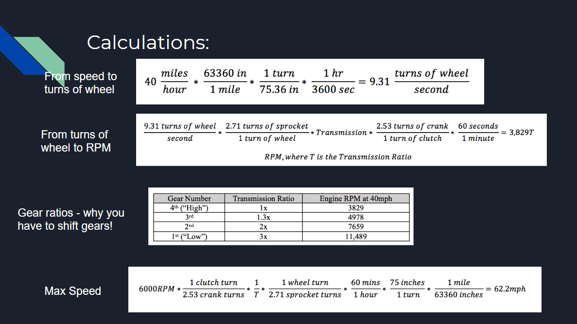

We did a set of calculations based on the gear ratios to see the revolutions per minute (RPM) of the engine at 40mph in each gear, and then the maximum speed of the motorcycle based on the engine’s max RPM of 6000. You can see in the chart that in low gear, the requisite engine speed to go 40mph quickly exceeds the engine’s maximum RPM. Shifting to high gear while you accelerate is very important!
Demo Gearing
