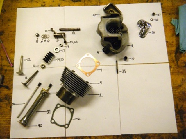
| Part # | Part Name |
| 1 | Cylinder Barrel |
| 2 | Cylinder Base Gasket |
| 3 | Piston |
| 4 | First Compression Ring |
| 5 | Second Compression Ring |
| 6 | Oil Control Ring |
| 7 | Gudgeoon Pin |
| 8 | Circlip |
| 9 | Cylinder Head |
| 10 | Cylinder Head Gasket |
| 11 | Exhaust Pipe Adapter |
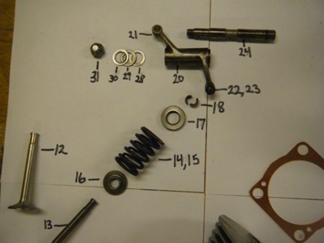
| 12 | Rocker Cover Stud |
| 13 | Carbirator Stud |
| 14 | Nut |
| 15 | Valve |
| 16 | Valve Guide |
| 17 | Circlip |
| 18 | Valve Spring (inner) |
| 19 | Valve Spring (outer) |
| 20 | Top Collar |
| 21 | Bottom Cup |
| 22 | Split Cotter |
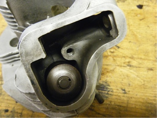
| 23 | Valve Rocker |
| 24 | Ball Ended Pin |
| 25 | Rocker Adjuster |
| 26 | Lock Nut |
| 27 | Rocker Spindle |
| 28 | Sealing Ring |
| 29 | Thrust Washer |
| 30 | Thrust Washer |
| 31 | Spring Washer |
| 32 | Rocker Cover |
| 33 | Rocker Cover |
| 34 | Cover Gasket |
| 35 | Retaining Nut |
| 36 | Copper Washer |
| 37 | Push Rod |
| 38 | Push Rod Tube |
| 39 | Washer |
| 40 | Washer |
| 41 | Tappet |
| 42 | Domed Nut |
| 43 | Copper Washer |
| 44 | Copper Washer |
How the Engine Works: The Otto Cycle
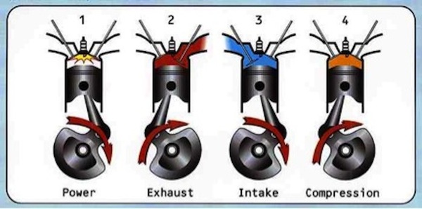
Intake Stroke (downward):
The cam and rocker mechanism opens the intake valve(the larger of the two valves) as the first piston stroke moves down the barrel. A mixture of fuel and air is sprayed through the intake valve and into the combustion chamber at the top of the engine. This is made possible almost entirely by the low pressure vacuum created by the downward stroke of the piston.
Compression Stroke (upward):
The piston makes its second stroke upward, compressing the fuel air mixture. Depending on the timing of the engine the spark plug will then spark just before the piston reaches the top of the stroke(advanced), exactly when it reaches the top of the stroke or just after it reaches the top of the stroke(retarded). The timing will be tuned according to the octane rating of the fuel, the atmospheric pressure of the location(ie the oxygen petrol ratio achieved by the carburetor among other things). We opted to use a regular cam instead of a racing cam which as we will show later determined which spring set we decided to use. The racing cam lengthens the time fuel is allowed to enter the combustion cylinder, so tighter springs are needed to snap the valves closed at the beginning and end of the intake and exhaust strokes.
Power Stroke (downward):
The fuel oxygen mixture explodes and pushes the piston down on its next stroke. The ratio of the volume of the cylinder before the stroke to the volume after the stroke is 1:9. The energy of each stroke corresponds to the pressure multiplied by the change in volume. The stroke transfers the energy from the explosion into rotational kinetic energy in the flywheel.
Exhaust Stroke (upward):
In the final upward stroke the cam-rocker mechanism opens the exhaust valve(the smaller valve) and the hot mixture of Carbon Dioxide, Sulfur Oxides, Nitric Oxides and incompletely combusted hydrocarbons leaves the chamber to the exhaust.
The cycle begins again.
Restoration and Repair Work:
Boring the Cylinder
One of the major problems with the top end was that the cylinder of the engine was too large for the piston. This compromises the efficiency of the engine and could allow oil to get into the combustion cylinder or carbon to get into the cylinder and would contribute to general wear and tear on the engine. As a result it was important to bore the engine cylinder.
What Boring is:
Bore is the measure of the diameter of the cylinder. With use, the cylinder wears unevenly and becomes slightly oval. Boring the cylinder makes it round again. This creates a better seal between the cylinder walls and the piston/piston rings. In turn this leads to a better compression ratio.
Process:
The barrel is mounted on the lathe and a bit is inserted with a sharp edge that shaves off very small amount of material. It does so equally at all points of the cylinder so that by the end the cylinder is perfectly round.
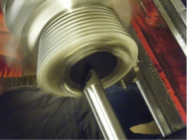
Our Engine:
Our cylinder was originally 20 over (0.02”). The piston and piston rings had a big gap however so we decided we needed to go up a piston size to 0.03” The gap needs to be small in order to seal the chamber and keep oil from leaking. Also, if there are sharp edges (such as the end of the rings if the gap is too big), heat will concentrate in these areas. In order for this piston to fit we began boring out the cylinder. As we proceeded however we notices a small axial crack that ran the entire length. We had to continue boring out small layers of material until finally the crack was gone. We then used a telescoping device to measure the new bore of the cylinder, only to realize it was slightly bigger than 0.03”. We did not want to bore the cylinder too far and risk compromising the walls but we still had a fair amount of room to work with. We continued boring until the cylinder was at 0.04” and we ordered a 40 over piston.
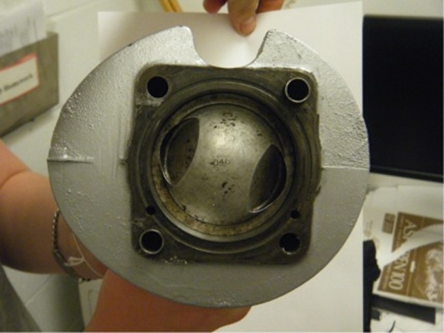
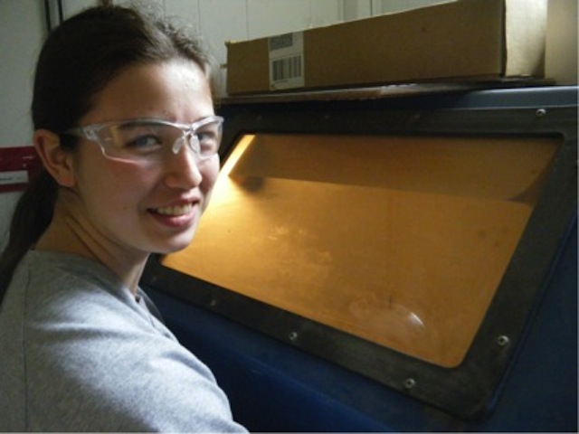
Sandblasting
To clean the barrel and head, a sandblaster was used to remove built up carbon and remove paint. The sandblaster is a sealed container with a window and two thick gloves. This allows you to safely move the object within the sandblaster. Underneath the grill is a funnel where all the sand pellets collect; this is where the suction tube picks up the sand. Sometimes the hose doesn’t pick up any sand, which can be caused by the suction tube not submerged in the sand or by the sand getting stuck.
After Sandblasting
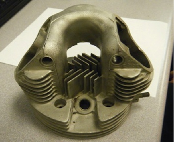
Spray Painting the Head and Barrel
We spray painted both the barrel and the head silver. To do this, all the openings, which the paint could have gotten into, were taped over, and a bit of oil was rubbed into the cylinder. The oil would prevent any paint that did get in from sticking to the metal. Then, by hanging the two pieces on a wire, we sprayed the paint on from all directions to make an even coating. Afterwards, we hung them up to dry. the spray paint used was specifically designed to withstand the high temperatures of a combustion engine.

Valves
The valves open and close to let air and gasoline into the combustion chamber. They also let emissions out of the engine. Pressures and temperatures become extremely high and it is important that the valves open swiftly and seal tight when they shut. It is very important to get two things right when servicing the valves; the alignment of the valve guides has to be perfect and the valve seats has to fit onto the valves perfectly so as to seal correctly.
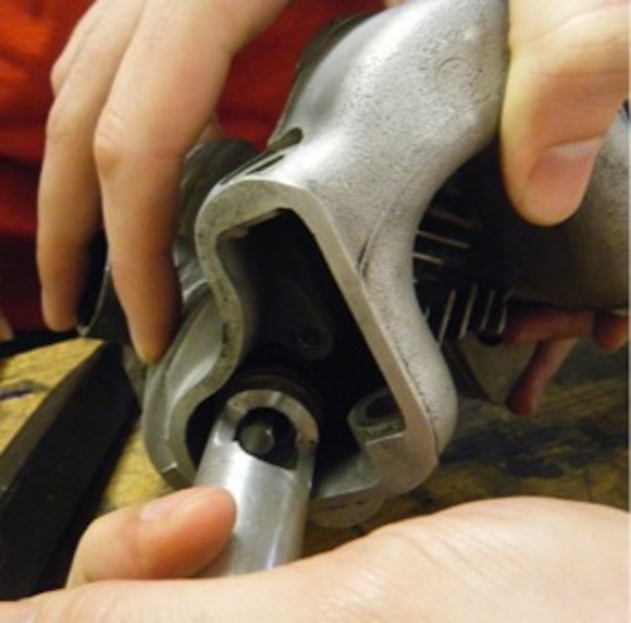
Glen assisted us with aligning the valve guides, since this had to be incredibly accurate and was awkwardly located on the inside of the engine head.
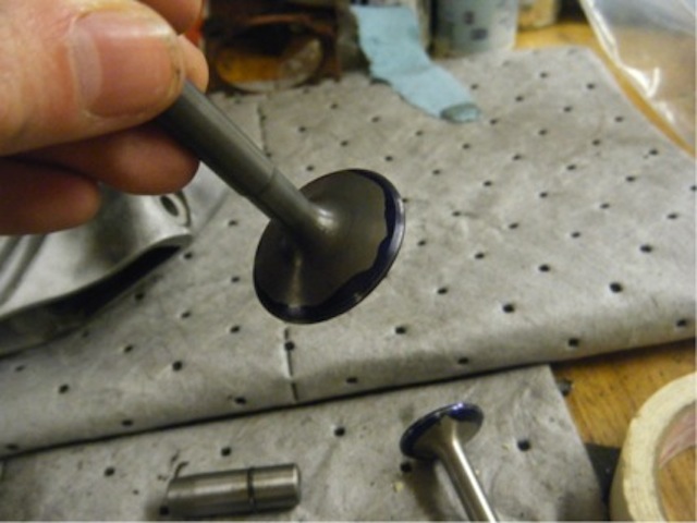
Preparing the Valve Seats
We were however able to prepare the valve seats. This involved cutting the valve seats with a specialized tool that resembled a spinning top mounted on a rod which ran through the valve guide. The “spinning top” had blades mounted on its sides at specific angles. First the valve was cut with the 46°blades and then the 60° blades. The work was tedious as the blades had to be rotated until no ridges could be felt. Once this was done the quality of the join was tested by “bluing” the valves. A heavily pigmented, alcohol based, blue solution was applied to the circumference of the valves and the valves were spun in place. A good “bluing” result is a narrow ring on or almost on the join between the 46° and 60° cuts. The cutting was repeated until the bluing result was good.

Next, an abrasive paste was applied to the surface of the valves and the valves were rotated in place. This was to ensure that the meet was complete all the way around the seat and that any inconsistencies were ironed out. Removing all of the abrasive after this step is incredibly important as any remnant abrasive could make its way into the combustion chamber and down the cylinder potentially causing damage to the cylinder.
Reassembly of the Head
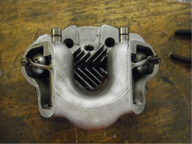
Determining the Spring Constants (k)
As mentioned before, it was important to determine the spring constant of the available sets of springs so that we could use the appropriate set (given that we were to use a normal cam, not a racing cam.) To find out the spring constants of the springs, a mechanical press was used to apply even and gradual pressure to the spring. The spring was put between the press and a force scale. By measure the compression (x) and the force applied (F), the k value could be determined using Hooke’s Law of F = -kx.

Old (Single) Springs
| Force applied (lbs) | Force (N) | Spring Length (in) | ΔX (in) | ΔX (m) | Spring Constant (k) |
| 0 | 0 | 1.71 | 0 | 0 | – |
| 11 | 48.928 | 1.625 | 0.085 | 0.002159 | 22662.34368 |
| 25 | 111.2 | 1.496 | 0.214 | 0.0054356 | 20457.72316 |
| 42 | 186.816 | 1.373 | 0.337 | 0.0085598 | 21824.80899 |
| 59 | 262.432 | 1.244 | 0.466 | 0.0118364 | 22171.60623 |
| Average k= | 21779.12051 | ||||
| k~ | 22000 N/m |
New (Double) Springs
| Force applied (lbs) | Force (N) | Spring Length (in) | ΔX (in) | ΔX (m) | Spring Constant (k) |
| 0 | 0 | 1.71 | 0 | 0 | – |
| 12 | 53.376 | 1.625 | 0.085 | 0.002159 | 24722.55674 |
| 63 | 280.224 | 1.496 | 0.214 | 0.0054356 | 51553.46236 |
| 87 | 386.976 | 1.373 | 0.337 | 0.0085598 | 45208.53291 |
| Average k= | 40494.85067 | ||||
| k~ | 40000 N/m |
Energy Per Explosion Calculations
Assuming:
- the intake valve allows 200cc air into the engine during each first downward stroke
- the air is at average atmospheric concentrations (CO2=21%)
- the gas is at standard temperature (25°C, 298K) and pressure (101.3 kPa)
- the mixture of Gasoline with Oxygen is perfectly stoichiometric
- the gasoline mixture is 87% Octane (by mass) (the remainder can be disregarded as alcohol additives and impurities which do not combust as readily as the gasoline)
This is of course heavily simplified. Full calculations would have to take into consideration the rate of flow of air into the cylinder (as determined by the valve timings) and therefore the actual volume of air taken in per stroke, the temperature of the gases present and the possible incomplete combustion of the fuel among other factors.
The moles of oxygen present for each explosion:
All gas:
PV = nRT
n = PV/RT
n = (101.325*200*10-6)/(8.31*298)
n = 8.18*10-3 moles
nO2 =n*0.21
=1.72×10⁻³ moles
C8H18 + 12.5O2 à 8CO2 + 9H2O
Therefore according to the reaction equation the moles of octane taken in per intake ought to be:
Nc8h18 = nO2/12.5
Nc8h18 = (1.72×10⁻³ )/12.5
Nc8h18 =1.38* 10-4 moles
Density( ρ ) = 730 kgm-3
= 730 000g/m3
Concentration = (% purity*ρ)/(Molar mass)
= (0.87*730000)/((8*12)+(18*1))
= 5.57 x10³ mol/m3
=5.57*10-3mol/cc
Volume gasoline necessary per stroke
= N/C
= (1.38* 10-4)/ ( 5.57×10⁻³)
= 2.48*10-5 << volume air
Thus may be considered negligible
The ΔHc of C8H18= −5.53–−5.33 MJ mol−1 ( http://en.wikipedia.org/wiki/Octane )
Thus the energy released in each explosion to these specifications
= ΔHc*N
~ (5.40×10⁶)( 1.38* 10-4)
~745.2 J per explosion
Additionally assuming that only 80% of the volume of the cylinder may fill with air( at 101KPa, 298K) in a given stroke due to rates of flow of air into the cylinder:
nO2 =1.72×10-3 *0.8
= 1.376 x10⁻³ moles
Nc8h18 = (1.376×10⁻³ )/12.5
= 1.1008×10⁻⁴ moles
Thus the energy released in each explosion = ΔHc*N
~ (5.40×10⁶)( 1.1008* 10-4)
~594.4 J per explosion