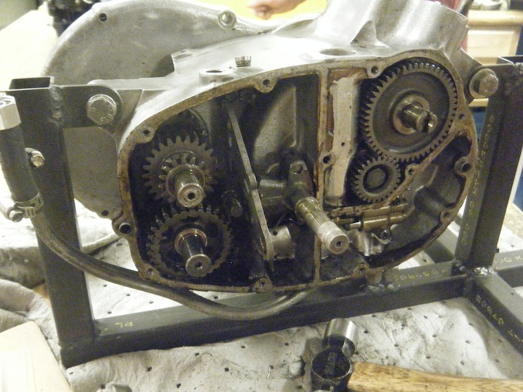
Unbuttoned Engine – Before
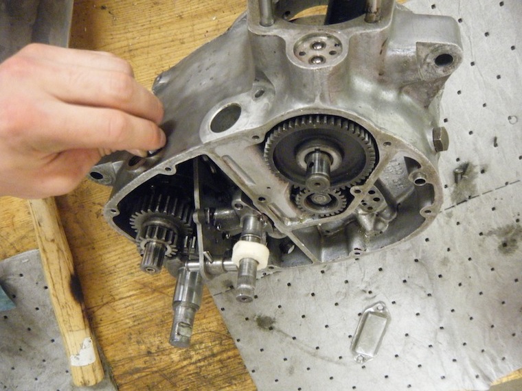
This is what the engine looked like without the engine covers before we removed any internal components. Shown is the transmission (left), the cam (right), the gear change spindle and shifter plate (middle), and the oil pump (starting under the cam, wrapping underneath to the left).
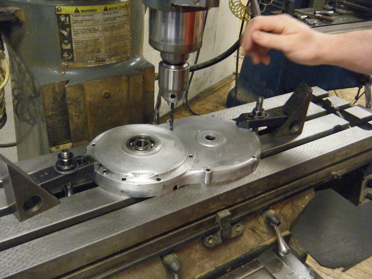
Finding Gasket Coordinates We used the milling machine’s XY plane to find the coordinates for all the screw holes in the engine cover. We then put those coordinates into the CAD program to create the shape that the laser would use to cut out the gasket.
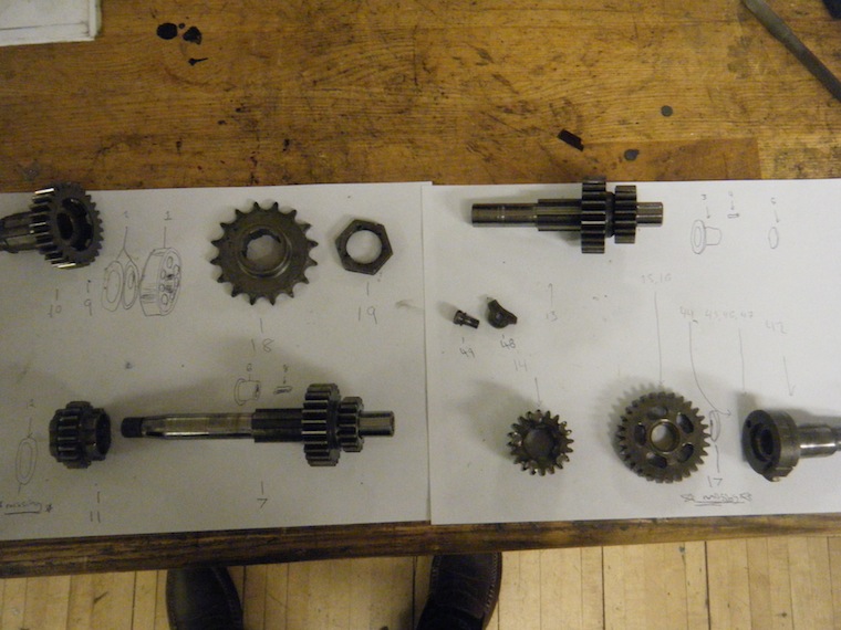
Transmission – Exploded View This is the exploded view of our transmission (the parts which remain inside the engine casing are drawn in). The transmission converts power from the flywheel rotation into power that turns the drive sprocket. The ratios for this specific motorcycle transmission are 2.72:1 for 1st gear, 1.56:1 for 2nd, 1.20:1 for 3rd, and 1.00:1.00 for 4th. Those ratios mean that every 2.72 turns of the input shaft yield 1 full turn of the output shaft when the bike is in first gear, 1.56 turns yield 1 turn when in second, and so on.
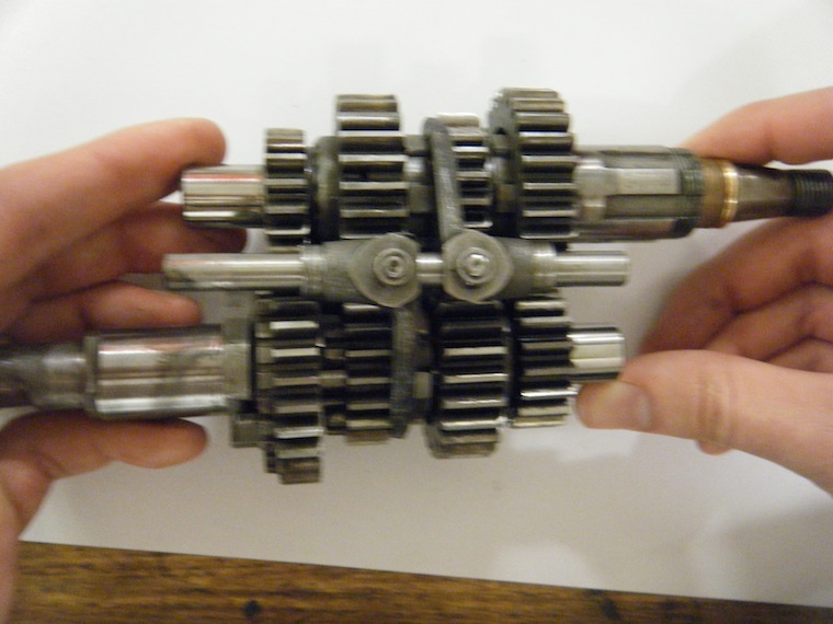
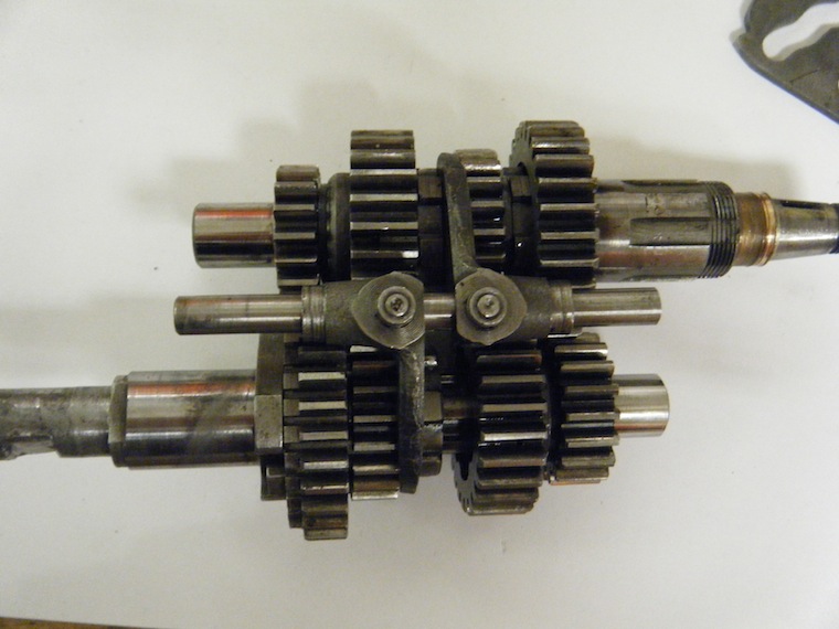
Transmission – Neutral This is the transmission assembled as it would be inside the engine in neutral gear, meaning that no gears are engaged and that as the input shaft spins the output shaft would remain static. The selector forks shown here slide the gears to the proper position for each gear.
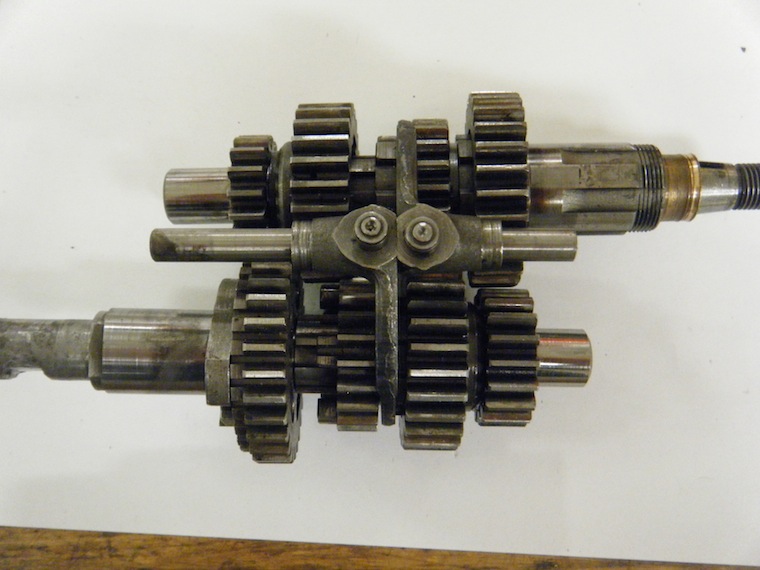
First Gear -This is the transmission assembled as it would be inside the engine in first gear. The selector fork has pushed the bottom gear to the left, engaging it with another gear, and putting the assembly in first gear.
Second Gear – This is the transmission assembled as it would be inside the engine in second gear. The selector fork has pushed the bottom gear to the right, engaging it with another gear, and putting the assembly in second gear.
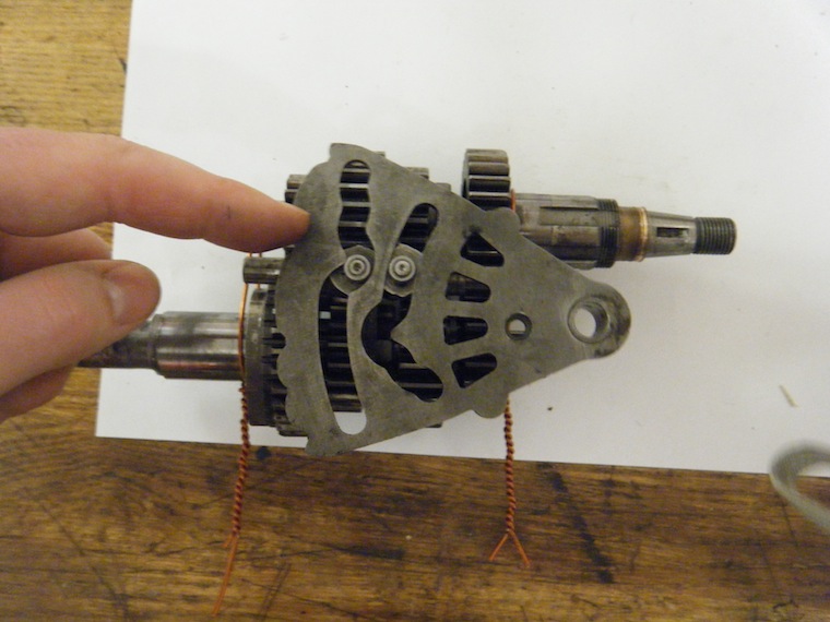
Third Gear – This is the transmission assembled as it would be inside the engine in third gear. The selector fork has pushed the top gear to the left, engaging it with the another gear, and putting the assembly in third gear. Also shown here is the shifter plate, which has channels to guide the rollers on the selector forks to the proper position. The notches on the end of the plate are called detents, and a spring inside the engine slips into those detents to lock the plate in place so that it will not accidentally slip out.
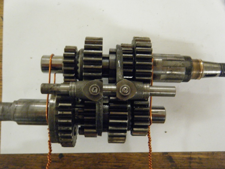
Fourth Gear – This is the transmission assembled as it would be inside the engine in fourth gear. The selector fork has pushed the top gear to the right, engaging it with another gear, and putting the assembly in fourth gear.
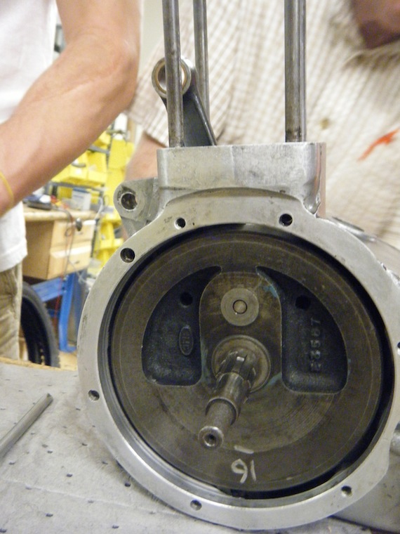
Shown here is the flywheel inside the engine casing. When the explosion in the barrel drives the piston downward, it pushes a rod which connects to the flywheel downward, too. The flywheel is very heavy so that it has enough momentum to use the energy from that one explosion to drive the piston three more strokes before the next explosion. The rotation of the flywheel transfers power to the input shaft of the transmission.
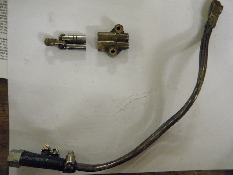
This is the oil pump assembly for our engine. Our engine has a dry sump, which means that the oil collects at the lowest point of the engine but sloshes around with air, too. The oil has to be separated from the air before it is redistributed throughout the engine. Our oil pump sucks in that air along with the oil and transports both to a reservoir. There the denser oil sinks to the bottom, separating itself from the air, and piping then delivers the oil from that reservoir to the engine.
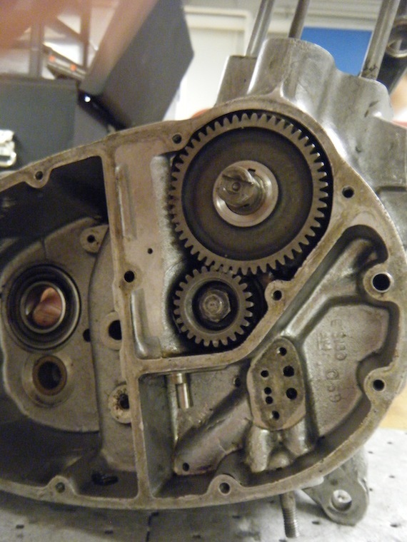
This shows the cam inside the engine. The cam has lobes attached which push tappets that in turn drive push-rods attached to valves. The valves control when oxygen enters the barrel, so the cam timing is crucial to an effective explosion in the engine.
This is the engine at the end of the course before we buttoned it back up. We cleaned every part and replaced the ones that were damaged. The engine currently runs quite well, so all in all it was a success.