Spark Advance Mechanism

Introduction
The spark advance is a mechanism in the electrical system which adjusts spark timing in the engine, adjusted based on RPM, in order to get the most efficient combustion. The spark advance uses spring force and centripetal force, attained through rotating weights, to contract the spark advance gap and adjust the timing. As the piston moves down, the spark causes the mixture of fuel and air to ignite. With each ignition and stroke, the timing must be adjusted to occur a little bit earlier each time. This is due to the higher rotation speeds of the engine which is related to the movement of the piston. Thus, understanding the spark advance mechanism is an essential part in understanding the performance of a motorcycle. Improper timing could cause engine damage among many issues.
Image Capture
This gap expansion happens between 0 and 2000 RPM. For this reason in order to capture the contraction of the mechanism we would need either a high speed camera or the ability to slow down the apparent motion. The latter was the approach we chose. In order to make the motion appear slower we used a strobe light whose pulse speed was half that of the rotation speed of the spark advance. This allowed us to effectively capture the spark advance at one place in its motion. This is because as it was flashing the frequency of the pulses and the rotation acted deconstructively bringing the image of the spark advance to a halt. Images were captured at rotation speeds from approximately 3000 RPM to 200 RPM in 100 RPM increments.
Image Processing
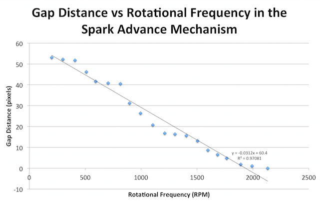
Using ImageJ, we measured the distance of the gap in pixels and plotted the gap distance as a function of the rotating speed of the lathe in Microsoft Excel, from 200 RPM up to 3000 RPM. The plotted points indicated a linear relationship as displayed below in figure 1.
To create the GIF, we imported all the images into Adobe Photoshop CS6. We rotated the images so that each picture was oriented similarly and could be overlaid. Using the frame animation tool, we displayed each image in the series for 0.05 seconds and exported it as a GIF video file, as shown in figure 2. The GIF shows the rotation speed increasing from rest up to 3000 RPM. As the speed increases, the gap similarly increases until approximately 2000 RPM. After 2000 RPM, the gap has already decreased to its minimum distance and does not continue to compress.
Discussion
Theoretically using a simple pivot, we would expect that the relationship between the gap and the rotation speed to be a quadratic relationship. In a simplistic model, the spring force, F = kx (k = spring constant, x = displacement), would be equal the to centripetal force, F = mrw^2 (m = mass, r = radius of rotation, w = angular velocity). Simplified, x is proportional to w^2.
Experimentally, we determined that the gap distance and rotation speed share a linear relationship. The occurrence of a linear relationship can be explained by the constraint mechanism used in the spark advance mechanism. While the weight moves and the gap increases, there is another plate, visible on the GIF, that also moves and stabilizes the movement to be linear.
Though modern electrical systems have transitioned to a computer-based paradigm, potential future experiments include adjusting the strength of the springs and the mass of the weights utilized and comparing their effect on the movement of the gap.