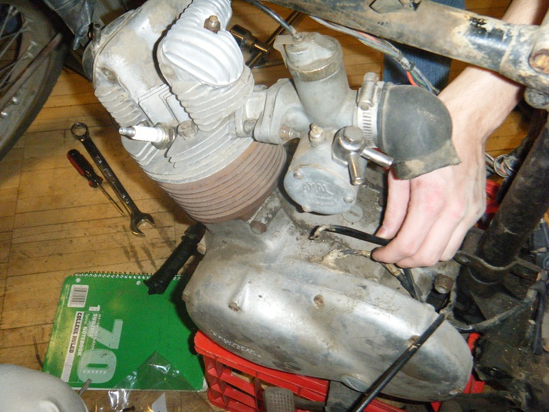
When we first started to disassemble the bike, the engine was one of the things that we focused on. Its importance to the success of the project is clear. The bike had been parked for several years prior to the time that it was purchased for the class. The picture gives a good idea of what kind of condition the exterior of the engine was in. The cylinder was rusty and some pieces were missing or had been replaced with nonstandard parts. However, it was a good starting point for restoring this bike.
The Triumph Tiger Cub has a 4 cycle engine with one cylinder. This means that one out of every four piston movements is the combustion of the gas and air mixture. The cycles are as follows:
1. Intake- the piston moves downward while the intake valve opens, creating suction which draws the fuel/air mixture into the cylinder.
2. Compression- the intake valve closes and the piston begins moving upwards again, compressing the gas/air mixture. This compression also heats the mixture. The amount of combustion is determined by the shape of the piston, which can be changed to alter compression ratios. A higher compression ratio puts more stress on the engine, and requires a higher octane gasoline, while also increasing engine performance. In our bike, we opted to use a piston with mid-level compression ratio, rather than Glenn’s 10.5 to one piston which would have required either leaded gasoline or extremely high octane fuel (higher than premium gasoline) to run properly in our system.
3. Power- the spark plug fires approximately when the piston is approximately at its highest point (top dead center) initiating combustion. The gas rapidly burns and increases pressure in the cylinder, pushing the piston back downwards.
4. Exhaust- the exhaust valve opens, and the gases remaining from combustion are pushed out by the pressure from the cylinder moving upward
The interaction of the piston and the valves determines max RPM, since at extremely high RPM the piston moves up and down so quickly in the cylinder that the valves cannot open and shut quickly enough.
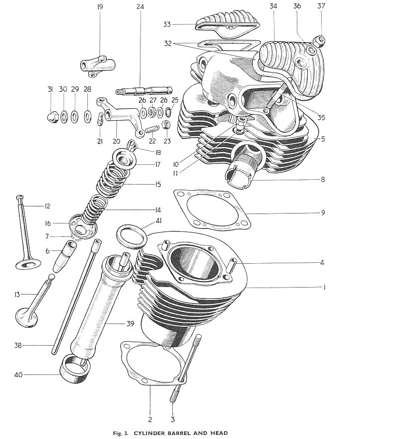
Cylinder and Piston
Crankshaft Assembly
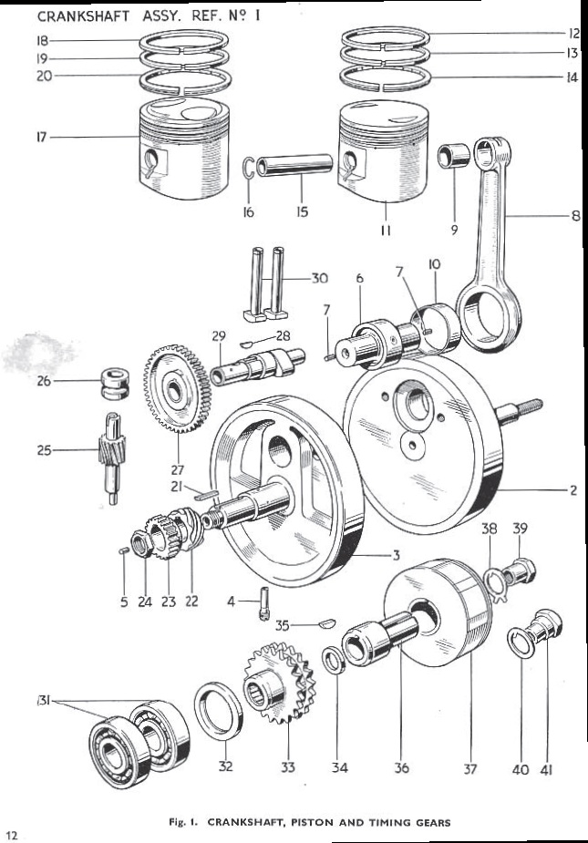
These two exploded views from the Triumph parts manual give a sense of the assemblies that compose the upper half of the engine. Some of the operation of the engine can also be divined. These diagrams correspond to the version of the Tiger Cub that succeeded the 1962 Cub. However, the proper ones will be posted once they can be accessed. The engine is a 200 cc displacement single-cylinder four-stroke. The engine also has overhead valves. This configuration was fairly advanced at the time of the motorcycle’s production. As can be seen from the images, every two rotations of the crankshaft corresponds to four one way cycles of the piston. The pinion gear on the crankshaft drives a corresponding gear on the camshaft. The step from 25 to 50 teeth causes the camshaft to rotate at half the speed of the crankshaft, so every rotation corresponds to one power stroke of the piston. The lobes on the camshaft push against the tappets which in turn push the valve pushrods. The pushrods rotate the rocker arms in the cylinder head. The rocker arms alternately open and close the intake and exhaust valves. These valves supply the engine with fuel and air for a power stroke and evacuate the exhaust on the following stroke. Since our bike is a high performance model, the intake valve is larger than the exhaust valve, so that more fuel and air can be drawn into the cylinder on the intake stroke.
Also in this diagram is the piston, which is used to create both high and low pressure (depending on the cycle) in the cylinder. The piston has three rings around it, with the top and bottom being used exclusively to create pressure, while the middle one is also used to distribute oil. The piston has a slight taper (the top end is skinnier) so that it fits well within the cylinder when hot from combustion. This is why a cold engine will generally not run as well as an engine that has already been heated up- once the engine is heated up the piston creates an optimal seal within the cylinder. The heat produced by combustion also influences the design of the cylinder. The cast iron cylinder has fins to dissipate the heat of combustion into the air flowing past the motorcycle. On the ’62 cub, the the fins were oval in shape while earlier models had round ones and later models featured square ones as shown in the drawing above. The aluminum cylinder head is also finned to transport heat away from the inside of the combustion chamber.
Disassembly
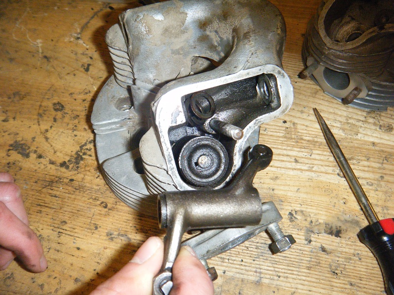
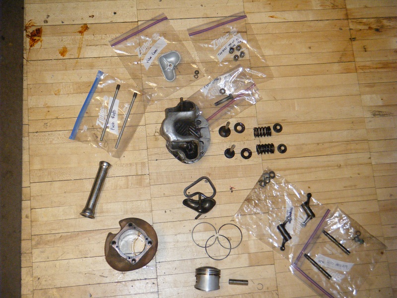
After the engine unit was removed from the frame, the cylinder head was unbolted and lifted off. The cylinder and piston were also removed from the lower end of the engine. Disassembely of the cylinder head began with the removal of the rocker covers. Next, the rocker arms were removed as can be seen in the picture. The picture also gives a better idea of the condition of the cylinder head. The valves were removed by compressing the valve springs with a C-clamp and a special tool while the clips holding the spring in place could be removed. This was a tricky operation, as the clips are small, but putting them back was much more difficult. With the valves removed, the top end of the engine was totally disassembled and restoration work could begin.
Completely Dissasembled Cylinder and Head
Restoration Work
Leaving it in Better Shape than We Found it in.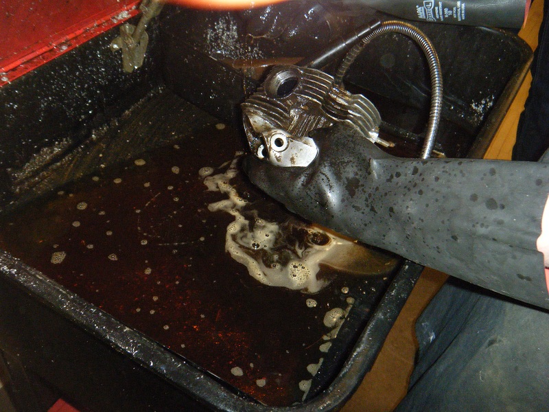
With the engine apart cleaning, the first step of restoration, could begin. Trying to clean the head in the parts cleaner was ineffective. Blasting it with an abrasive glass bead media proved to be much more effective and cleaned it up pretty nicely. Most of the the other parts that were reused were simply wiped down prior to the start of reassembly. The piston had to discarded because the diameter of the cylinder bore was too great for the piston.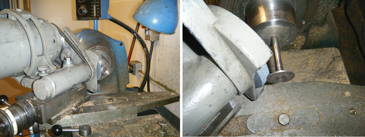
Repair work on the top end of the engine includes resurfacing of the valves, cutting of new valve seats, and boring the cylinder. The valve surfaces needed to be refinished in order to properly seal the cylinder and yield optimum performance. The valves were reworked using a grinder and a lathe as in the picture. New valve seats were also cut into the cylinder head. Instead of a single 45 degree angle as would have been usual, the new valve seats were cut to 31, 46, and 61 degrees. This three-angle valve job results in a smaller contact area between the valve and the seat. This characteristic results in a better performing and more durable arrangement. The valve seats were cut by hand using a kit designed especially for the purpose. After the proper dimensions were obtained, the seats were lapped by placing grinding compound on the valve and rotating it against the seat to even out the surfaces and provide an even tighter seal. The valves were then replaced. The purpose of this work was to create a good seat for the valves, which now contact their seats in small, thin circles. In determining how much of the valve hits the seat, we struck a happy medium between two competing ideas. A very small contact area would have high performance for a short amount of time, since it would seal very well but would have poor heat dissipation. On the other hand, a larger contact area would have better heat dissipation but would make a worse seal.
The next step in the overhaul will be to bore the cylinder to 0.060 in. over standard. This step is necessary because the engine was poorly bored previously. When it was bored previously, the person who did the work cut it to exactly .040 over and didn’t hone it to remove the boring marks. As the engine was run, the piston gradually wore down the small grooves from the previous boring, making the cylinder significantly larger and robbing the engine of power. This is extremely unfortunate, because it means that we will be required to bore the engine to .060 over, which is the maximum amount that can be done, since the quality of metal in the engine deteriorates the further we bore from the center. The engine will need to be replaced if it requires any more boring. A new 0.060 over piston with a 9:1 compression ratio has been ordered. With this step, the overhaul of the top end of the engine will be nearly complete. Stay tuned for updates as the project progresses.