Students:
Joshua Theodore ’23
Abstract
This project taught me the importance of pivoting in a venture in the face of unexpected obstacles. For this project I started out with the lofty ambition of 3D modeling and 3D printing three accessories that would upgrade my Exway Atlas electric skateboard, however, due to inadequate funding and resources, I was forced to change directions several times. Initially, the goal was to create a bash guard for the front of the electric skateboard, a custom griptape design made from shock-absorbing grip tape, as well as a set of fenders that would be compatible with 105mm diameter polyurethane wheels with a 60mm contact patch. Due to a reduction in budget from $75 to $65 the bash guard as well as the grip tape was not able to be produced. To replace this aspect of the project I designed and produced wheel pulleys for a set of boosted 105mm wheels which I purchased with my own money. This process required several iterations as there were key dimensions of the wheel pulley then needed to be exact. This included the ten pins that are inserted into the wheel to attach the pulley to the wheel as well as the whole for the bearing.
Design Ideas
The following are the relevant design ideas I came up with for skateboard accessories.
Grip Tape

An aesthetically pleasing design was going to be designed and cut out of Dope Grip PRO grip tape and added to the skateboard. This grip tape is said to have excellent traction regardless of riding conditions. This means that even if dirt, water, or mud got on the grip tape it would not lose its grip. It will keep your feet from slipping. In addition, it has a layer of high-tech refined machine cushion, that adsorbs road vibrations as well as allows one’s feet to sink into the grip tape for added stability and grip.
Nose Guard
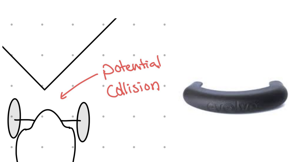
Although the front wheels of the board extend past the nose of the skateboard, this nose is still exposed to potential damage from corner collisions. As a result, I thought it necessary to create a nose guard that protects the skateboard from direct impacts.
Fenders
Whether the ground is wet, or muddy, I ride on dirt trails, or on paved roads, there is always a chance that debris will be transferred from the ground to the top of the deck of the skateboard or to my clothing. To counteract this, I designed fenders which prevent debris from dirtying my clothing or the top of the deck.
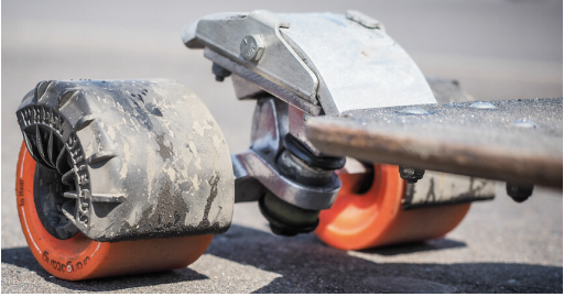
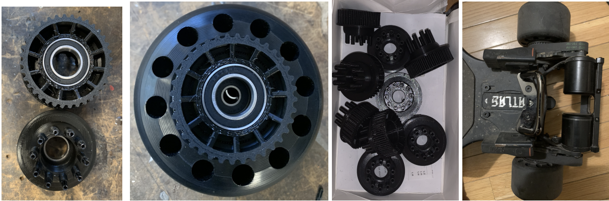
Wheel pulleys
In order for the skateboard motors to drive the skateboard wheels, it requires motor pulleys, belts, and wheel pulleys. The motor pulleys spin at the same rate as the motor, the belt transfers power from the motor pulley to the wheel pulley, and the wheel pulley spins at the same angular velocity as the wheel. By adjusting the size of the wheel pulley one can achieve different gear ratios which allow for variation in top speed and acceleration. I designed a 5M gear pulley that meshes perfectly with the Boosted 105 wheel to create a 14:38 gear ratio. This allows for a top speed of 32 mph while maintaining acceptable acceleration As mentioned in the introduction only the fender and the wheel pulleys were developed due to
inadequate funds.
Final Components design process
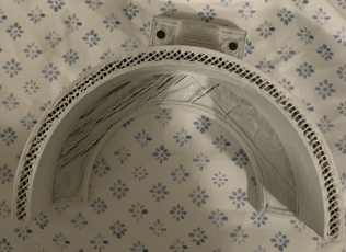
Fender
First, the skateboard geometry was measured to determine which holes and clearances needed to be maintained. After which an initial sketch containing all the salient dimensions was created. Next, a model of the skateboard geometry was created in fusion 360. This model was used to design the first iteration of the fender design.
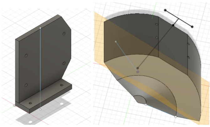
During the testing of the first iteration, it was determined that this design was two complicated because it had several unnecessary screws which had the potential to shake loose. The geometry of the part was incorrect which resulted in insufficient clearance around the wheel. This clearance was necessary because vibrations in the skateboard will likely cause the fender to shake, meaning that without proper clearance it could hit the wheel. Additional small debris could get lodged in between the fender and the wheel without the necessary clearance. A clearance of 1cm was chosen. Since both myself and my lab AI were unfamiliar with Fusion 360, I switched to Creo parametric in which I created a simplified design.
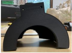
This simplified version of the design still had the clearance issue. In addition, part of the print failed, so I was unable to test part of the design geometry. This caused me to create another design. This design failed, leaving me just enough time to make one more attempt which I did not have time to pick up and test.
Wheel pulley
For this design I looked online for a wheel pulley to base my design off of, unfortunately, it was hard to find step files. I found step files of a 39-tooth pulley and a 36-tooth pulley. I used the step files as a base and modified the geometry to fit the Boosted 105 wheel. I first printed the 39 tooth pulley, however, I got some of the tolerances wrong. After fixing the tolerance I learned that I did not have a belt large enough to accommodate the pulley, as a result, I switched to a 36t pulley design. When I printed it, the tolerance was not correct and I had to adjust it once more. Additionally, I was having an issue with support material interfering with the part of the pulley that interfaced with the teeth. I then pushed steel rods into the pinholes where the wheel and pulley meshed, however, the pulley was out of round and resulted in the belt tension varying as the wheel rotated, this caused me to remake the pulley in a resin printer. Since this material was more prone to fracture, I pushed copper-plated welding rod into the pinholes rather than hollow oversized steel pins because I did not want to start cracks that could propagate and cause the pins to fail. These pulleys were successful enough for me to use them on my electric skateboard to get around campus. I only had enough time to make one pulley from the resin printer. As a result, I am currently using one pulley made from PLA and the other made from a gray pro. The uneven belt tension from the PLA pulley causes occasional vibration when riding as well as decreases the strength of the breaks.
Materials list
3D Printing Material
– PLA
– Gray pro
Other materials
– Welding rod
– 20 Slotted steel spring pins
– Pulley bearing
– Wheel bearing
Future Direction
In the future, I plan on improving the wheel pulley so that the belt tension is constant when the wheels rotate. This may require slight adjustment of the wheel pulley geometry as well as finding a printer on campus that will not print it out of round. I also plan on editing the design of the fender so that it has a more aerodynamic design. After testing the fender I plan on modifying additional aspects of the design so that they perform like a finished product. This may include modifying the thicknesses of certain parts as well as the shape in order to prevent unwanted vibrations, sounds, and failures.